Three-Axis Magnetic Sensor and Method for Manufacturing the Same

a magnetic sensor and three-axis technology, applied in the field of three-axis magnetic sensors, can solve the problem of not having the desired characteristics of z-axis sensors, and achieve the effect of accurately determining the direction of a magnetic field, easy and inexpensiv

Inactive Publication Date: 2009-01-29
YAMAHA CORP
View PDF13 Cites 114 Cited by
  • Summary
  • Abstract
  • Description
  • Claims
  • Application Information

AI Technical Summary

Benefits of technology

[0018]Then, the present invention has been made for solving the above problems, and an object thereof is to provide a three-axis magnetic sensor with such a constitution as to be simply and easily fabricated on one chip (one substrate).
[0042]In the method for manufacturing the magnetic sensor, after the step of magnetizing the permanent magnet film connected to the magnetoresistive effect elements of the Z-axis by using a magnet array having a plurality of permanent magnet pieces arranged so as to be different in polarity for each of the adjacent permanent magnet pieces to align the four corners of the cell of the substrate with the adjacent permanent magnet pieces of the magnet array, the step of magnetizing the permanent magnet film connected to the magnetoresistive effect elements of the X-axis and the Y-axis by moving the substrate to align the substrate with the permanent magnet pieces of the magnet array is conducted, thereby the magnetoresistive effect elements of the Z-axis will not undergo any change in the polarization state even in magnetizing the magnetoresistive effect elements of the X-axis and the Y-axis. Thereby, there will be no difference in sensitivity between the magnetoresistive effect elements of the X-axis and the Y-axis and the magnetoresistive effect elements of the Z-axis, providing easily and inexpensively a magnetic sensor capable of accurately determining the direction of a magnetic field in three-dimensional directions (X-axis direction, Y-axis direction and Z-axis direction).

Problems solved by technology

Further, when Z-axis sensors are only given the same film constitution and a similar treatment of regularization by using conventional permanent magnet pieces, it is impossible to provide Z-axis sensors having desired characteristics, which is a problem.

Method used


Image

  • Three-Axis Magnetic Sensor and Method for Manufacturing the Same
  • Three-Axis Magnetic Sensor and Method for Manufacturing the Same
  • Three-Axis Magnetic Sensor and Method for Manufacturing the Same

Examples


first embodiment

[0183]First, an explanation will be made of a three-axis magnetic sensor of a first embodiment as follows by referring to FIG. 1A to FIG. 15C.

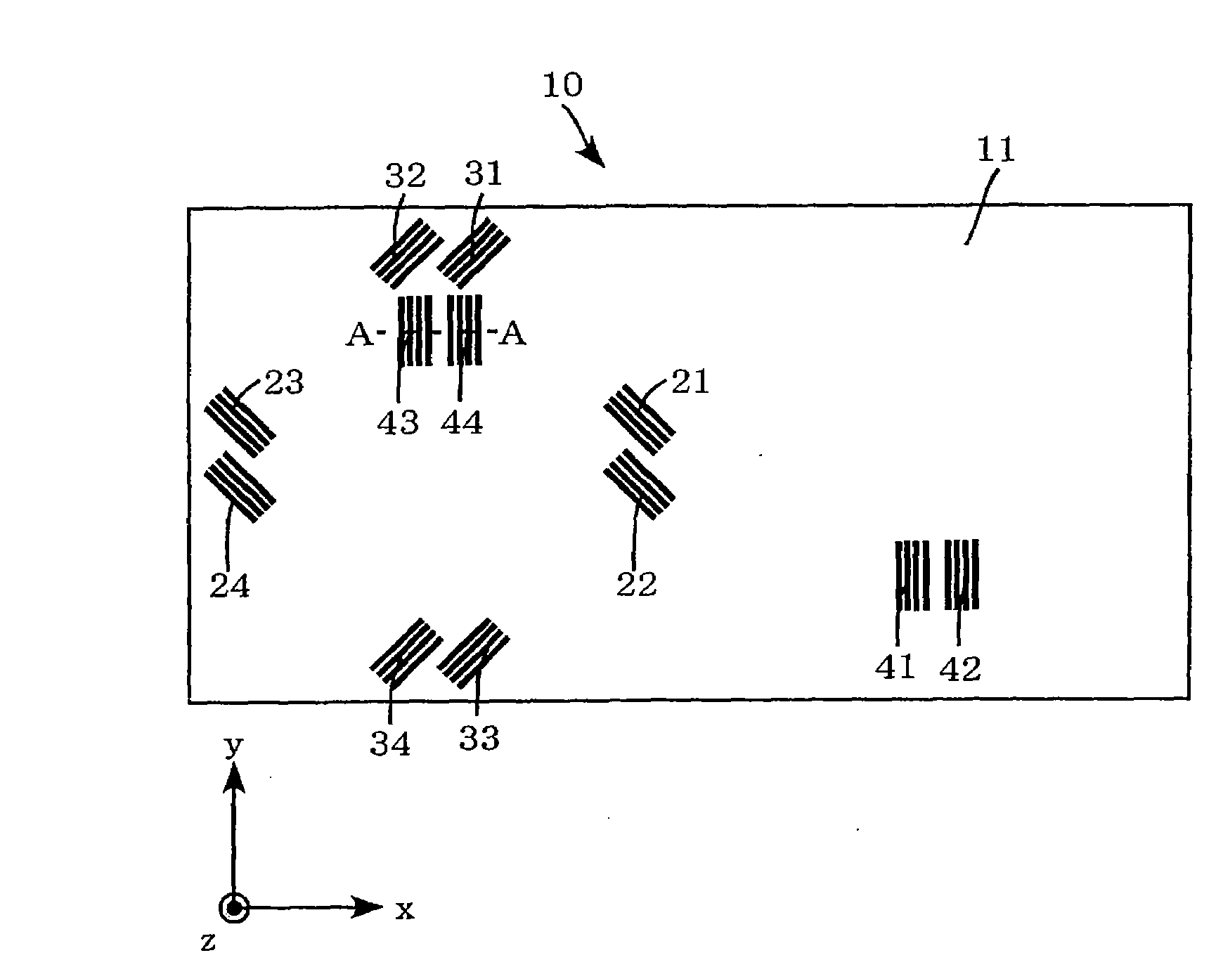
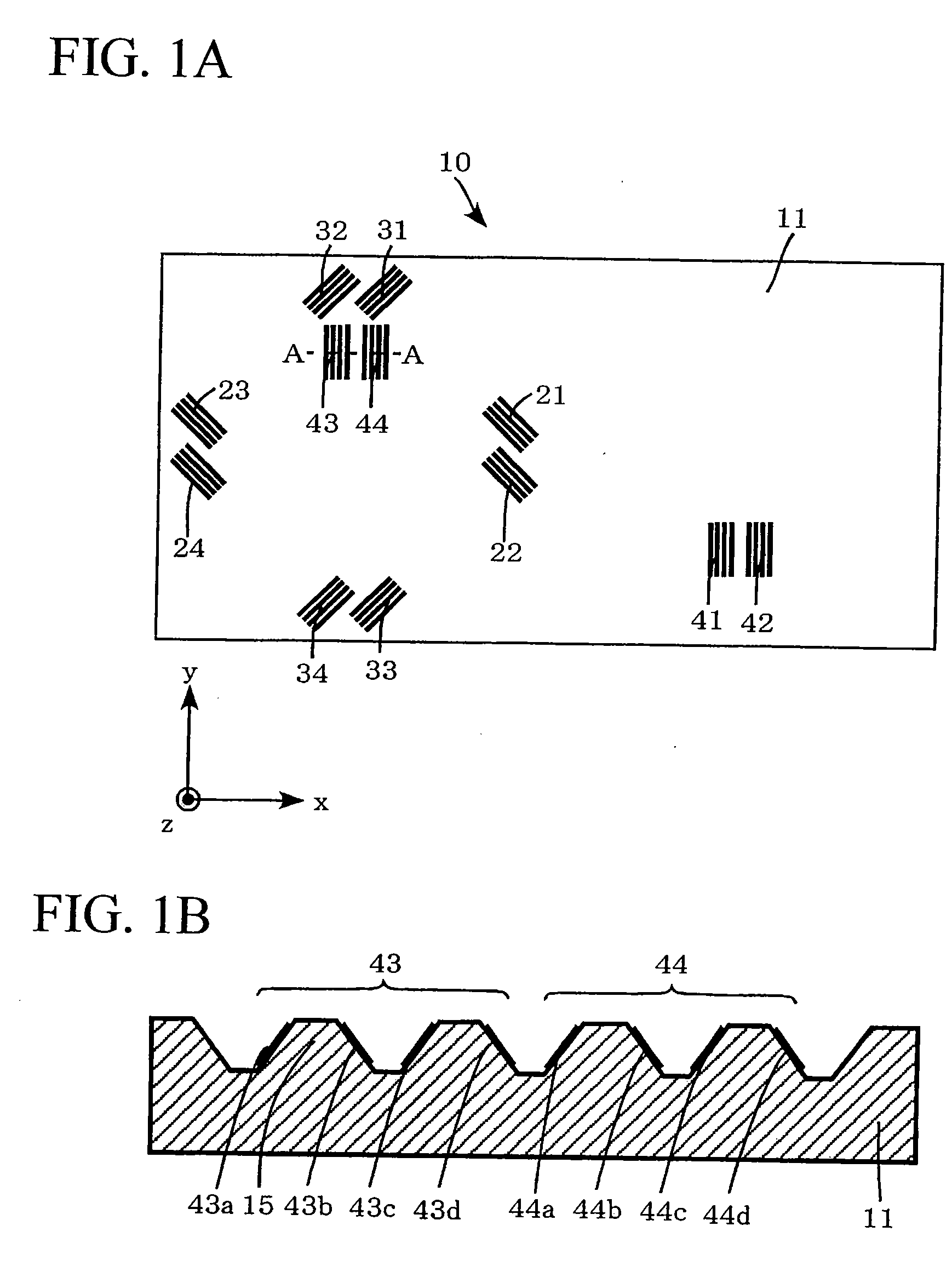
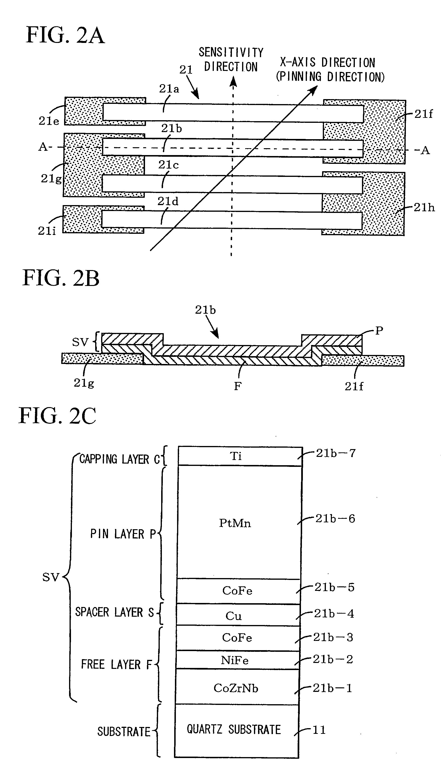
[0184]As illustrated in FIGS. 1A and 1B, a three-axis magnetic sensor 10 of the first embodiment is provided with a substrate 11 made up of quartz or silicon, which is in a rectangular shape, with the sides along the X-axis and Y-axis orthogonal to each other, when viewed from above, (here, it is shaped so that the ratio of the short side (longitudinal) to the long side (transverse) (aspect ratio) is 1:2 and the side along the X-axis is a long side and the side along the Y-axis is a short side) and has a small thickness in the direction of the Z-axis orthogonal to the X-axis and the Y-axis. Then, a total of 12 GMR elements respectively made up of four elements of X-axis GMR elements 21 to 24, Y-axis GMR elements 31 to 34 and Z-axis GMR elements 41 to 44, a total of 12 pads (not illustrated) and connecting wires (not illustrated) connecting eac...

second embodiment

[0228]Next, an explanation will be made of a three-axis magnetic sensor of a second embodiment as follows by referring to FIG. 17A to FIG. 20C.

[0229]As illustrated in FIGS. 17A and 17B, a three-axis magnetic sensor 60 of the second embodiment is provided with a substrate 61 made with quartz or silicon which is in a rectangular shape with the sides along the X-axis and Y-axis orthogonal to each other, when viewed from above (here, it is shaped so that the ratio of the short side (longitudinal), to the long side (transverse) (aspect ratio) is 1:1.5 and the side along the X-axis is a long side and the side along the Y-axis is a short side) and has a small thickness in the direction of the Z-axis orthogonal to the X-axis and the Y-axis. It is possible to make the present sensor smaller in dimension than the three-axis magnetic sensor of the first embodiment by using the above-described substrate 61.

[0230]Then, a total of 12 GMR elements made up of respectively four elements of X-axis GM...

third embodiment

[0255]Then, an explanation will be made of the three-axis magnetic sensor of a third embodiment as follows by referring to FIG. 21A to FIG. 24B.

[0256]As illustrated in FIGS. 21A and 21B, a three-axis magnetic sensor 70 of the third embodiment is provided with a substrate 71 made with quartz or silicon which is in a square shape having the sides along the X-axis and Y-axis orthogonal to each other, when viewed from above, (namely, half in dimension as compared with the substrate 11 of the first embodiment) and has a small thickness in the direction of the Z-axis orthogonal to the X-axis and the Y-axis. It is possible to make the present sensor smaller in dimension than the three-axis magnetic sensor of the first embodiment and that of the second embodiment by using the above-described substrate 71.

[0257]Then, a total of ten GMR elements, namely, four each of the X-axis GMR elements 71a to 71d and the Y-axis GMR elements 71e to 71h and two Z-axis GMR elements 71i to 71j formed on a su...


PUM

PropertyMeasurementUnit
voltageaaaaaaaaaa
magnetoresistive effectaaaaaaaaaa
magnetizationaaaaaaaaaa

Abstract

In the three-axis magnetic sensor of the present invention, a plurality of magnetoresistive effect element bars are connected in series by means of bias magnets to constitute magnetoresistive effect elements, and magnetoresistive effect elements of the X-axis sensor and those of the Y-axis sensor are formed on a flat surface parallel to the flat surface of the substrate. The sensitivity direction of magnetization is a direction vertical to the longitudinal direction of each of the magnetoresistive effect element bars, and magnetoresistive effect elements of the X-axis sensor and those of the Y-axis sensor are formed in such a way that the magnetization directions are orthogonal to each other. Further, magnetoresistive effect elements of the Z-axis sensor are formed on a tilted surface of the projection projected from the flat surface of the substrate in such a way that the magnetization direction is inside the tilted surface. The Z-axis sensor is provided in such a way that the sensitivity direction is vertical to the longitudinal direction of the magnetoresistive effect element bar.

Description

TECHNICAL FIELD[0001]The present invention relates to a three-axis magnetic sensor provided with an X-axis sensor to which a plurality of magnetoresistive effect elements are bridge-connected, a Y-axis sensor to which a plurality of magnetoresistive effect elements are bridge-connected and a Z-axis sensor to which a plurality of magnetoresistive effect elements are bridge-connected within one substrate, and also relates to a method for manufacturing the three-axis magnetic sensor.[0002]Priority is claimed on:Japanese Patent Application No. 2005-77010 filed Mar. 17, 2005;Japanese Patent Application No. 2005-90581 filed Mar. 28, 2005;Japanese Patent Application No. 2005-91256 filed Mar. 28, 2005;Japanese Patent Application No. 2006-32124 filed Feb. 9, 2006; andJapanese Patent Application No. 2006-32125 filed Feb. 9, 2006, the contents of which are incorporated herein by reference.BACKGROUND ART[0003]Giant magnetoresistive elements (GMR elements), tunneling magnetoresistive elements (T...

Claims


Application Information

Patent Timeline
Patent Type & Authority Applications(United States)
IPC IPC(8): G01R33/09G01R3/00
CPCB82Y25/00G01R33/09Y10T29/49002H01L27/22Y10T29/4902G01R33/093H10B61/00H10N59/00H10N50/10
Inventor SATO, HIDEKIOMURA, MASAYOSHINAITO, HIROSHIOOHASHI, TOSHIYUKIWAKUI, YUKIOOSUGA, CHIHIRO
Owner YAMAHA CORP
Why Eureka
Try Eureka