Radio transmission device, and radio transmission method

a radio transmission device and radio transmission technology, applied in the field of radio transmission apparatus and radio transmission method, can solve the problems of inability to receive stations successfully, and achieve the effect of preventing the deterioration of preamble detection performance and reducing the collision ra

Active Publication Date: 2009-01-29
PANASONIC INTELLECTUAL PROPERTY CORP OF AMERICA
View PDF5 Cites 38 Cited by
  • Summary
  • Abstract
  • Description
  • Claims
  • Application Information

AI Technical Summary

Benefits of technology

[0014]The present invention makes it possible to reduce the RACH collision rate and prevent deterioration of preamble detection performance.

Problems solved by technology

If the transmission resources overlap between a plurality of users and their RACH's collide, the base station cannot receive these successfully, and the mobile stations have to retransmit the RACH's.

Method used


Image

  • Radio transmission device, and radio transmission method
  • Radio transmission device, and radio transmission method
  • Radio transmission device, and radio transmission method

Examples


embodiment 1

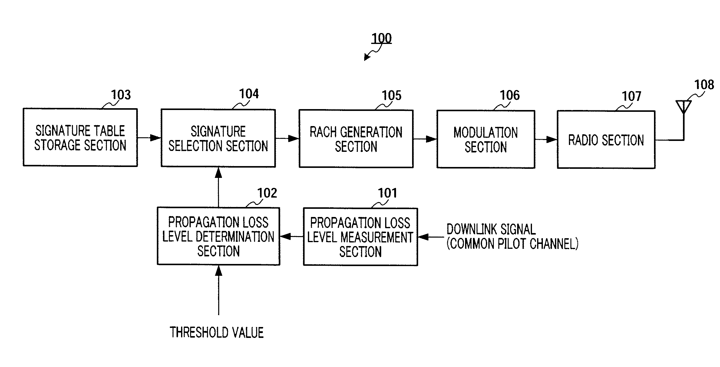
[0032]FIG. 4 is a block diagram showing the configuration of transmitting apparatus 100 according to Embodiment 1 of the present invention. Referring to this figure, propagation loss level measurement section 101 calculates the propagation loss level (attenuation of signal power [dB]) by measuring the received power for a downlink signal (common pilot channel) and subtracting the measured received power from known transmission power. The calculated propagation loss level is outputted to propagation loss level determination section 102. The common pilot channel has its transmission power determined in advance by the system and is transmitted with fixed power.

[0033]Propagation loss level determination section 102 makes a threshold decision between the propagation loss level outputted from propagation loss level measurement section 101 and certain threshold values set in advance. Two different threshold values of threshold Th1 and threshold Th2 that is lower than Th1, are used here, an...

embodiment 2

[0050]A case will be assumed with Embodiment 2 of the present invention where a plurality of RACH transmission slots (herein after “RACH slots”) of different bandwidths are adopted as shown in FIG. 10. Here, broadband RACH slots (for example, 5 MHz bandwidth) and narrowband RACH slots (for example, 1.25 MHz bandwidth) are prepared in FDM or TDM. The broadband RACH slot and the narrowband RACH slot have the same slot length.

[0051]FIG. 11 is a block diagram showing the configuration of transmitting apparatus 200 according to Embodiment 2 of the present invention. FIG. 11 is different from FIG. 4 in that transmission band control section 202 is added and signature table storage section 103 is changed to signature table storage section 201.

[0052]In FIG. 11, signature table storage section 201 associates the propagation loss levels of “high” and “low” with respective cyclic shift values and transmission bandwidths, and stores a table (i.e. signature table) where signatures generated from...

embodiment 3

[0057]With Embodiment 3 of the present invention, a case will be explained employing the ZCZ-GCL (Zero Correlation Zone-Generalized Chirp Like) sequence.

[0058]First, the ZCZ-GCL sequence will be explained. The ZCZ-GCL sequence Ci(k) is represented by the following equation 3:

[1]

Ci(k)=a(k)bi(k mod m), k=0,1, . . . , N−1, i=0,1, . . . , m−1  (Equation 3)

where N is the code length, and, N=sm2 (s and m are integers).

[0059]Moreover, a(k) is referred to as the “carrier sequence” and is represented by the following equation 4.

[2]

a(k)=WNk(k+N mod 2) / 2+qk, k=0,1, . . . , N−1  (Equation 4)

[0060]where WN=exp(j2πγ / N), γ and N are coprime integers, and q is an integer.

[0061]bi(k) is referred to as the modulation sequence, and, as to the ZCZ-GCL sequence, the Hadamard sequence of the following equation 5 or the DFT (Discrete Fourier Transform) sequence of the following equation 6 is generally used. The code length of the modulation sequence is m, and there are m kinds of sequences.

[3]bi(k)=(-1)∑l...


PUM


Abstract

Provided are a radio transmission device and a radio transmission method, which prevent the deterioration of a preamble detecting performance while reducing the collision probability of a RACH. In this radio transmission device, a Signature table storage unit (103) divides the magnitudes of transmission loss levels into individual levels corresponding to the distances from a base station, to cause CAZAC series and circulation shift quantities to correspond to each other at the individual levels, and is provided with a table containing a plurality of Signatures created from the CAZAC series and the circulation shift quantities caused to correspond to each other. A Signature selecting unit (104) selects one of the corresponding Signatures at random from the Signature table storage unit (103), on the basis of the magnitude of the transmission loss level outputted from a transmission loss level deciding unit (102). A RACH signal generating unit (105) generates the RACH signal with the Signature selected.

Description

TECHNICAL FIELD[0001]The present invention relates to a radio transmitting apparatus and radio transmission method for transmitting the RACH (Random Access Channel).BACKGROUND ART[0002]Currently, in 3GPP RAN LTE (Long Term Evolution) studies are being conducted for a RACH transmission method. The RACH refers to an uplink channel which a mobile station uses upon transferring from idle mode to a calling step and to transmit information required to establish a scheduled channel to the base station. The RACH cannot be scheduled by the base station, and so a mobile station takes the initiative in randomly selecting transmission resources (e.g. code pattern). If the transmission resources overlap between a plurality of users and their RACH's collide, the base station cannot receive these successfully, and the mobile stations have to retransmit the RACH's.[0003]In LTE, including at least a signature, which is terminal identification information, into the RACH, is studied. Moreover, as the ...

Claims


Application Information

Patent Timeline
Patent Type & Authority Applications(United States)
IPC IPC(8): H04L12/26H04B1/707H04J13/10H04W72/04
CPCH04J13/0055H04J13/0066H04J13/0062
Inventor IWAI, TAKASHIIMAMURA, DAICHIMIYOSHI, KENICHIFUTAGI, SADAKIMATSUMOTO, ATSUSHITAKATA, TOMOFUMI
Owner PANASONIC INTELLECTUAL PROPERTY CORP OF AMERICA
Why Eureka
Try Eureka