Method and apparatus for sampled optical signal monitoring

a technology of optical signal and sampling method, applied in the field of optical performance monitoring, can solve the problems of high frequency signature, low accuracy, and low accuracy of typical clock extraction circuit, and achieve the effects of reducing receiver bandwidth, high frequency signature, and high receiver bandwidth

Inactive Publication Date: 2009-01-29
NICTA IPR
View PDF7 Cites 56 Cited by
  • Summary
  • Abstract
  • Description
  • Claims
  • Application Information

AI Technical Summary

Benefits of technology

[0039]Preferably, the or each optical receiver used to detect the optical signal has a receiver bandwidth which is greater than or equal to the bandwidth of the optical signal. A high receiver bandwidth is advantageous in that signatures of impairments (such as dispersion) may potentially be more evident in the high frequency components of the waveform.
[0040]However, in alternate embodiments, the receiver bandwidth may be less than the signal bandwidth, for example as low as substantially ¼ of the signal bandwidth, or substantially less than ¼ Of the signal bandwidth. While a reduced receiver bandwidth loses high frequency signatures, it has been recognised that there is still significant information in two point asynchronous sampling with such reduced receiver bandwidths. Indeed, reduced receiver bandwidths may assist in separating or fi

Problems solved by technology

Such time domain techniques are sensitive to signal distortion and noise.
Not only does clock extraction involve added expense, a typical clock extraction circuit only works over a limited range of bit rates and

Method used


Image

  • Method and apparatus for sampled optical signal monitoring
  • Method and apparatus for sampled optical signal monitoring
  • Method and apparatus for sampled optical signal monitoring

Examples


Embodiment Construction

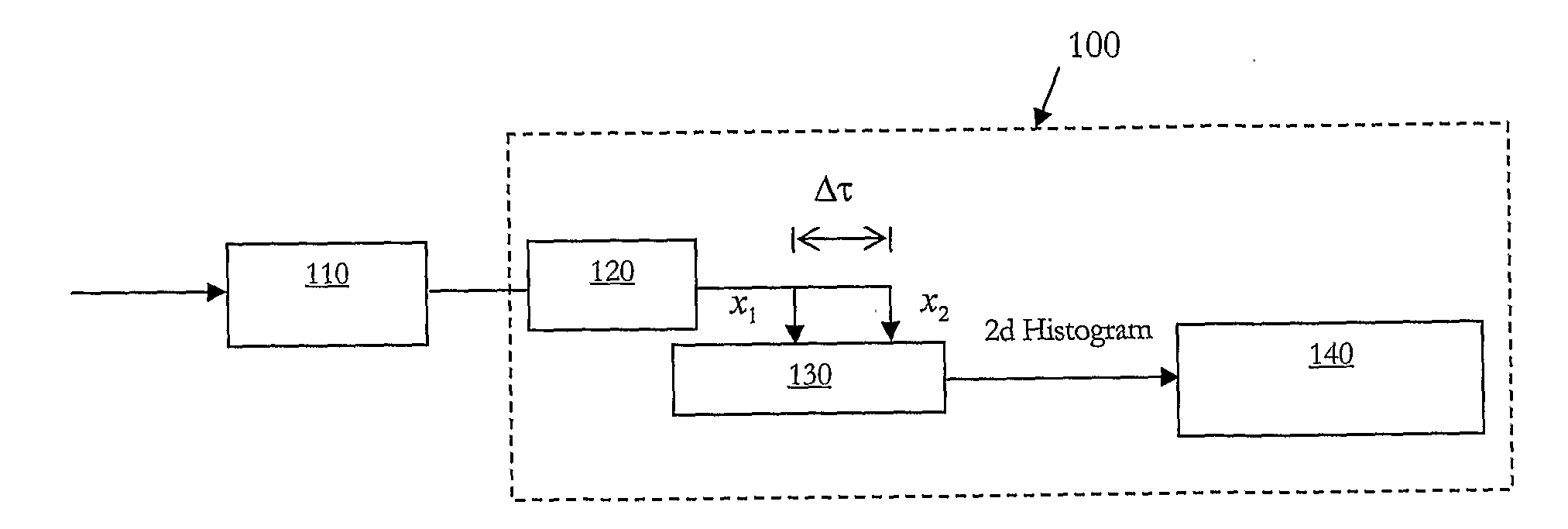
[0111]FIG. 1 is a schematic of a two tap asynchronous sampling optical signal monitor 100 in accordance with the present invention. A small amount of optical power is tapped from a DWDM signal and the optical channel to be monitored is selected by a tunable optical filter 110 and then detected by a high speed receiver 120. The receiver output is passed through a two tap delay line and asynchronously sampled by a dual channel A / D sampler 130, and the sample pairs (x1,n, x2,n) are then passed to a processor 140 to build a probability density function of numerous such sample sets. If x(t) denotes the optically demultiplexed channel then the sample pairs are given by:

x1,n=x(nTs)

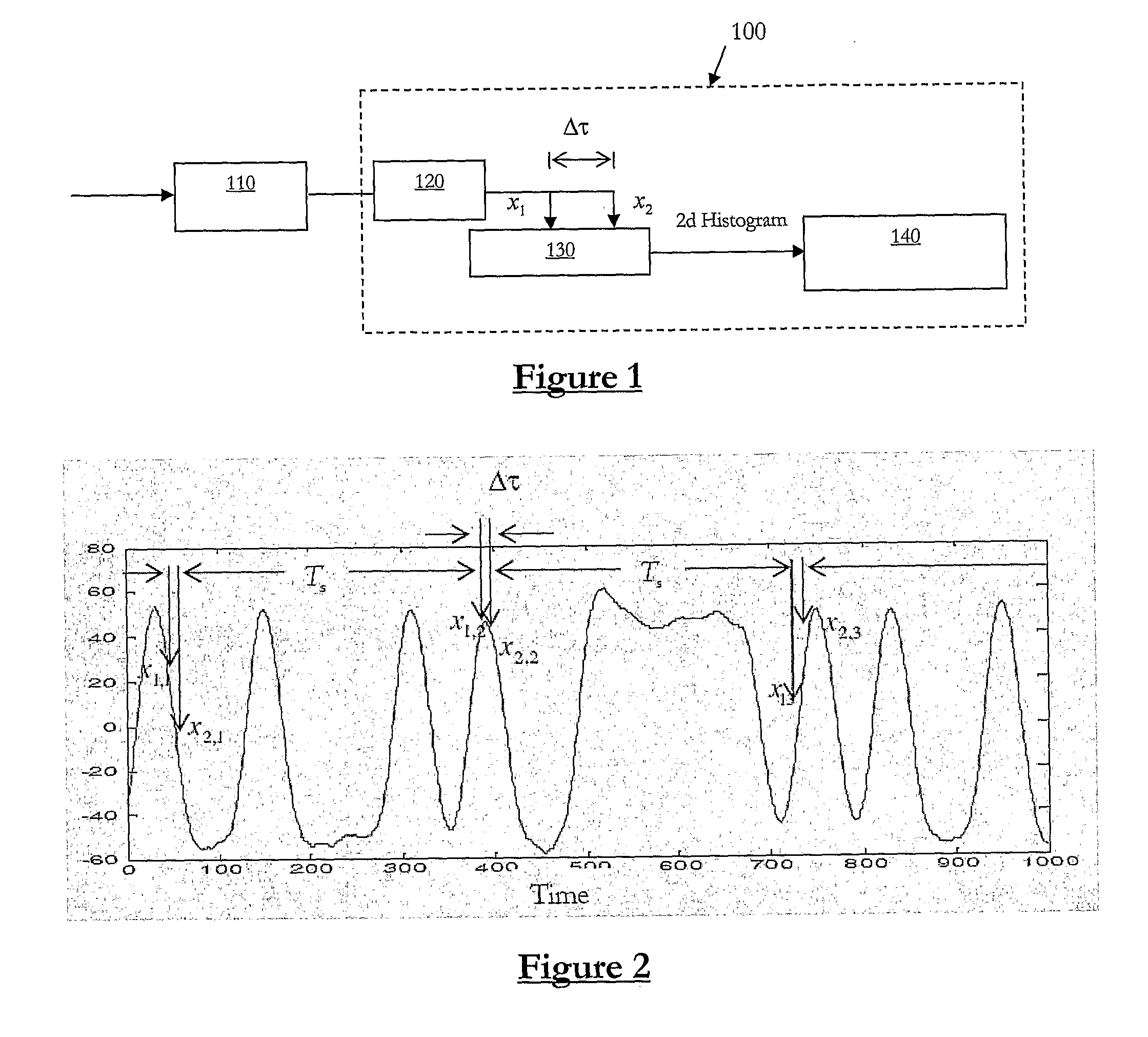
x2,n=x(nTs+Δτ)[0112]where Δτ denotes the time between taps and 1 / Ts is the sampling rate. The monitor 100 of FIG. 1 provides a simple implementation of the present invention, by use of a simple two tap delay line after the optical receiver 120 so as to effect the tap delay Δτ in the electrical domain.

[0113]FIG. 2...


PUM


Abstract

Monitoring an optical signal comprises sampling the optical signal from two or more distinct tap points to retrieve a sample set. Multiple such sample sets are obtained over time. A joint probability distribution or phase portrait of the sample sets is assessed for indications of optical signal quality. The tap distinction can be polarisation, for example to determine OSNR, or frequency. The tap distinction can be a time delay, which can enable diagnostic differentiation between multiple impairments, such as OSNR, dispersion, PMD, jitter, Q, and the like. Machine learning algorithms are particularly suitable for such diagnosis, particularly when provided a two dimensional histogram of sample density in the phase portrait.

Description

CROSS-REFERENCE TO RELATED APPLICATIONS[0001]The present application claims priority from Australian Provisional Patent Application No 2005905668 filed on 13 Oct. 2005, Australian Provisional Patent Application No 2006901088 filed on 3 Mar. 2006, and an Australian Provisional Patent Application filed on 5 Oct. 2006, the contents of which are incorporated herein by reference.TECHNICAL FIELD[0002]The present invention relates to optical performance monitoring, and in particular relates to a sampling technique for retrieving optical signal quality information.BACKGROUND OF THE INVENTION[0003]Optical performance monitoring is becoming increasingly important, particularly in dense wavelength division multiplexed (DWDM) optical communication systems. The main drivers for signal monitoring are to identify changes in transmitted signals, to diagnose the cause and location of the underlying faults, to optimize the performance of tunable elements, and to estimate the bit-error rate (BER).[000...

Claims


Application Information

Patent Timeline
IPC IPC(8): H04B10/08G06F17/18
CPCH04L7/0054
Inventor ANDERSON, TREVORDODS, SARAHKOWALCZYK, ADAMBEDO, JUSTINCLARKE, KENNETH PAUL
Owner NICTA IPR
Why Eureka
Try Eureka