
Implantable heart stimulation device with remedial response to anodal capture

a heart stimulation and anodal capture technology, applied in heart stimulators, electrotherapy, therapy, etc., can solve the problems of unfavorable cardiac vein electrode fixation into the myocardium, and unfavorable cardiac vein electrode fixation

Inactive Publication Date: 2009-01-29
ST JUDE MEDICAL
View PDF12 Cites 46 Cited by
  • Summary
  • Abstract
  • Description
  • Claims
  • Application Information

AI Technical Summary

Benefits of technology

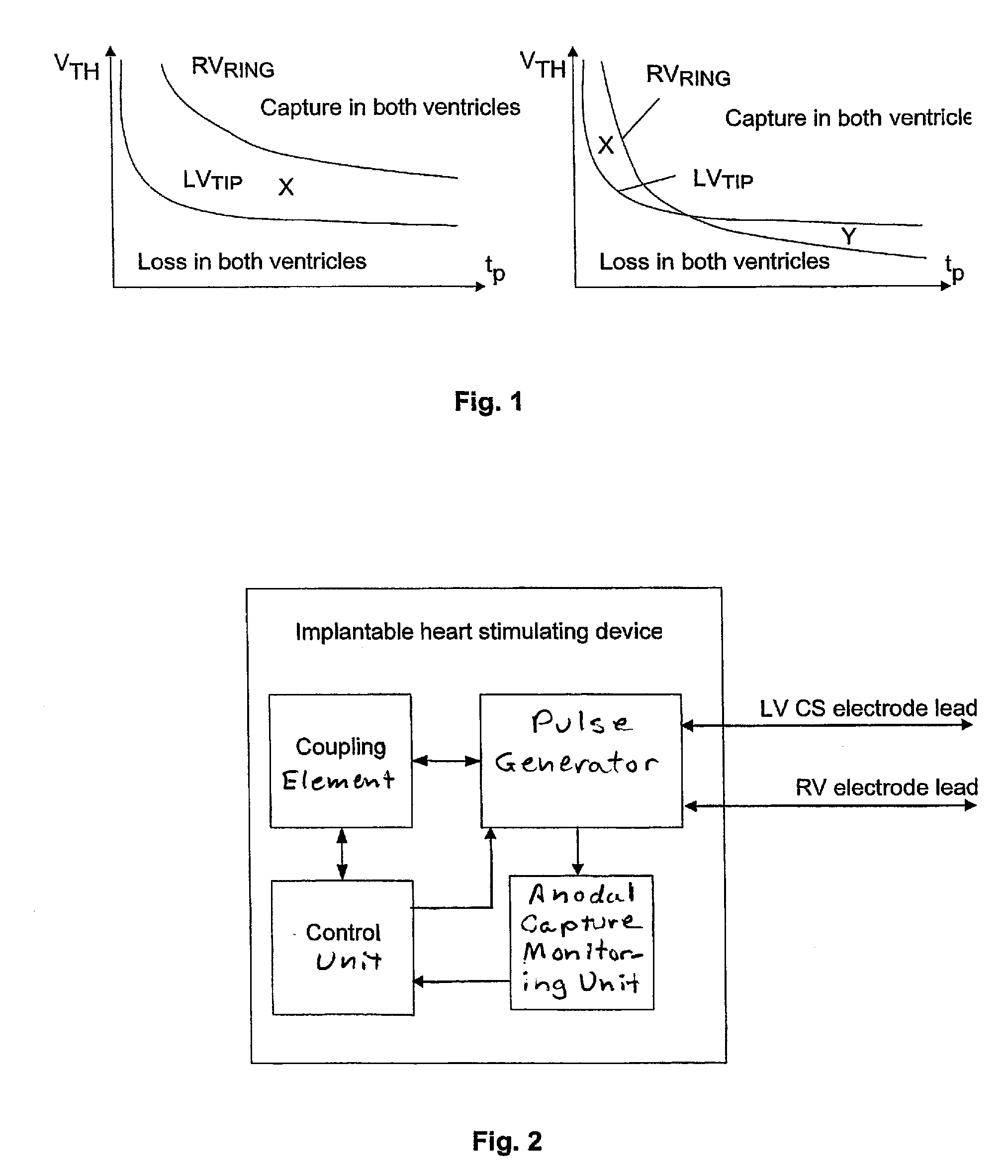
[0025]The above object is achieved in accordance with the present invention by an implantable heart stimulating device having a left ventricular (LV) coronary sinus (CS) electrode lead that carries a tip electrode, a right ventricular (RV) electrode lead that carries a ring electrode, and a pulse generator connected to these leads that applies a stimulation pulse between the tip electrode and the ring electrode, with the tip electrode serving as the cathode. A monitoring unit monitors for and detects anodal capture at the RV ring electrode subsequent to a stimulation. If anodal capture at the RV ring electrode is detected, either a threshold search is performed by varying the pulse width and / or pulse amplitude of the stimulation pulses in order to identify stimulation pulse characteristics that avoid anodal capture at the ring electrode, or at least one further electrode is employed as an indifferent electrode together with the ring electrode, also to avoid anodal capture at the ring electrode.

Problems solved by technology

If the left ventricle is stimulated first which it often is-both ventricles will depolarize at the same time and a ventricle-ventricle (VV) delay optimization is then not possible to perform.
Furthermore, an automatic capture algorithm may detect loss of capture at each RV stimulation since the RV has already been stimulated and is thus refractory.
This, in turn, will lead to unnecessarily going into high output mode and incorrect diagnostics.
Unlike a lead for the right ventricle, which is disposed within the ventricle where a tip electrode can be fixed into the myocardium, the electrodes of a lead in a cardiac vein cannot be fixed into the myocardium since that would require puncturing the vein.
A problem arises when the pulse energy for a bipolar lead in a cardiac vein is adjusted.
When the clinician then determines the capture threshold of the lead with a bipolar pulse in order to adjust the stimulus pulse energy, it is impossible to distinguish between anodal and cathodal capture.
There is then a risk that the stimulus pulse energy will be set to an anodal capture threshold when the cathodal capture threshold is higher.
As the anodal capture threshold increases over time, the stimulus pulses may no longer be of sufficient energy to excite the left ventricle (diminishing or eliminating the programmed safety margin), and the patient may experience sporadic or total loss of resynchronization therapy.
It has been found that a direction of the electrical stimulation vector, resulting from a stimulation pulse from an electrode close to nervus pherenicus, that essentially encompasses the nerve, may result in a nerve stimulation that in turn may cause diaphragm contractions.
Another reason is that if unipolar stimulation is applied using the housing (case) of the implantable device as indifferent electrode to a LV CS tip electrode, unwanted pocket stimulation may occur, i.e. anodal stimulation at the indifferent case electrode.

Method used


Image

  • Implantable heart stimulation device with remedial response to anodal capture
  • Implantable heart stimulation device with remedial response to anodal capture

Examples


Embodiment Construction

[0028]As stated above the present invention concerns an implantable heart stimulating device, in particular a biventricular pacemaker system, where LV stimulation is performed between the LV-tip (cathode) and the RV-ring (anode).

[0029]In a bi-ventricular pacing system, a small diameter, often unipolar, left ventricular (LV), coronary sinus (CS) electrode lead and a bipolar right ventricular (RV) endocardial electrode lead are preferably employed to provide left and right heart chamber pacing / sensing electrodes. The LV CS lead is advanced through the superior vena cava, the right atrium, the ostium of the coronary sinus (CS), the CS, and into the coronary vein descending from the CS to locate the LV active pace / sense electrode at a desired LV pace / sense site.

[0030]The RV electrode lead is advanced into the RV chamber to locate RV tip and ring electrodes therein.

[0031]A requirement that makes non-simultaneous biventricular pacing and VV-delay optimization is that no anodal ring stimul...


PUM


Abstract

An implantable heart stimulating device has a left ventricular coronary sinus electrode lead provided with a tip electrode, a right ventricular electrode lead provided with a ring electrode, and a pulse generator connected to the leads that applies stimulation pulses between the tip electrode and the ring electrode, with the tip electrode serving as the anode. A monitoring unit monitors for and detects anodal capture at the right ventricular ring electrode subsequent to a stimulation. If anodal capture is detected, either a threshold search is performed by varying the pulse width and / or pulse amplitude of stimulation pulses in order to identify stimulation pulse characteristics that avoid anodal capture at the ring electrode, or at least one further electrode is activated to function as an indifferent electrode together with the ring electrode, also in order to avoid anodal capture at the ring electrode.

Description

BACKGROUND OF THE INVENTION[0001]1. Field of the Invention[0002]The present invention relates to an implantable heart stimulating device, and in particular to a biventricular implantable heart stimulating device with which left ventricular (LV) stimulation is performed between an LV-tip electrode, being the cathode, and a right ventricular (RV) ring electrode, being the anode.[0003]2. Description of the Prior Art[0004]When stimulating LV-tip to RV-ring in a biventricular system a so called anodal stimulation generating an anodal capture may occur on the RV-ring. If the left ventricle is stimulated first which it often is-both ventricles will depolarize at the same time and a ventricle-ventricle (VV) delay optimization is then not possible to perform.[0005]Furthermore, an automatic capture algorithm may detect loss of capture at each RV stimulation since the RV has already been stimulated and is thus refractory. This, in turn, will lead to unnecessarily going into high output mode an...

Claims


Application Information

Patent Timeline
Patent Type & Authority Applications(United States)
IPC IPC(8): A61N1/368
CPCA61N1/371A61N1/3684A61N1/36843
Inventor HOLMSTROM, NILSBJORLING, ANDERS
Owner ST JUDE MEDICAL
Learn More