Capacitively coupled dielectric barrier discharge detector

a dielectric barrier and capacitively coupled technology, applied in the field of gas detectors, can solve the problems of large cost, difficult use, and inability to achieve the effect of reducing power and less power

Inactive Publication Date: 2009-02-05
CAVITON
View PDF6 Cites 22 Cited by
  • Summary
  • Abstract
  • Description
  • Claims
  • Application Information

AI Technical Summary

Benefits of technology

[0010]The general object of this invention is to provide an improved gas detector. More particular objects are to provide a gas detector that is smaller and uses less power than existing gas detectors. Another object of this invention is to provide an improved gas chromatography system.
[0011]We have invented an improved gas detector, comprising a tubular inner electrode with a left end and a right end, an inside and an outside; a dielectric tube coaxial with the inner electrode, the dielectric tube with a left end and a right end, an inside and an outside, the right end of the inner electrode inside the left end of the dielectric tube; a tubular outer electrode coaxial with the inner electrode and the dielectric tube, the outer electrode with a left end and a right end, an inside and an outside, the right end of the dielectric tube inside the left end of the outer electrode; the inner electrode adapted to allow a gas to flow therethrough, and the dielectric tube adapted to allow the gas to flow therethrough; the dielectric tube serving as a dielectric barrier between the inner electrode and the outer electrode; a longitudinal gap between the left end of the outer electrode and the right end of the inner electrode; the electrodes adapted to connect to an AC voltage supply creating a voltage between the outer electrode and the inner electrode, the voltage acting across the longitudinal gap and through the dielectric barrier, the voltage creating a continuous plasma discharge within the gas; and a sensor adapted to detect changes in optical properties of the gas as it passes through the gap.
[0012]The gas detector of this invention is smaller and uses less power than existing gas detectors, while providing long-lived devices previously unachievable. Both optical and electrical signals can be measured from the discharge to serve as a time-dependent signal which generates a chromatograph. Geometrical, optical, and electrical variations can be applied to the device to alter its signal-to-noise ratio, sensitivity, dynamic range, and linearity.

Problems solved by technology

No other analytical technique is as powerful and as generally applicable as is gas chromatography.
These detection techniques often alter the compounds.
In particular, specific detectors giving mass or atomic species information tend to be large, expensive, and difficult to use.
Non-specific detectors tend to be simple to use and inexpensive, but do not provide information about the chemicals being detected.

Method used


Image

  • Capacitively coupled dielectric barrier discharge detector
  • Capacitively coupled dielectric barrier discharge detector
  • Capacitively coupled dielectric barrier discharge detector

Examples


Embodiment Construction

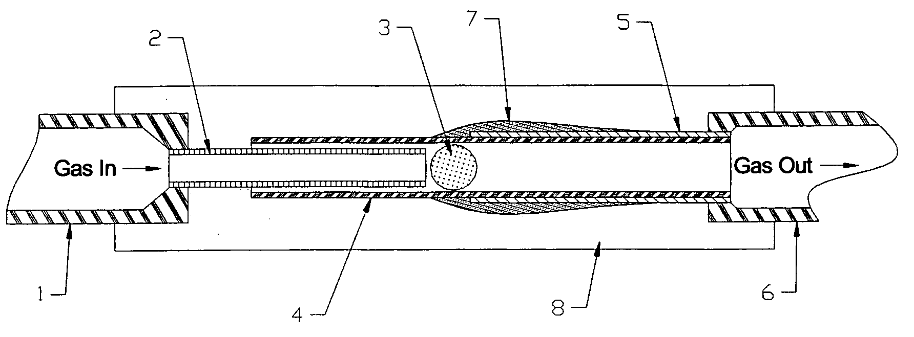
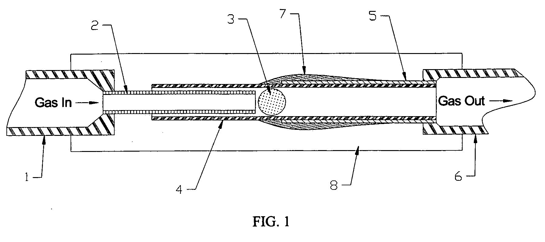
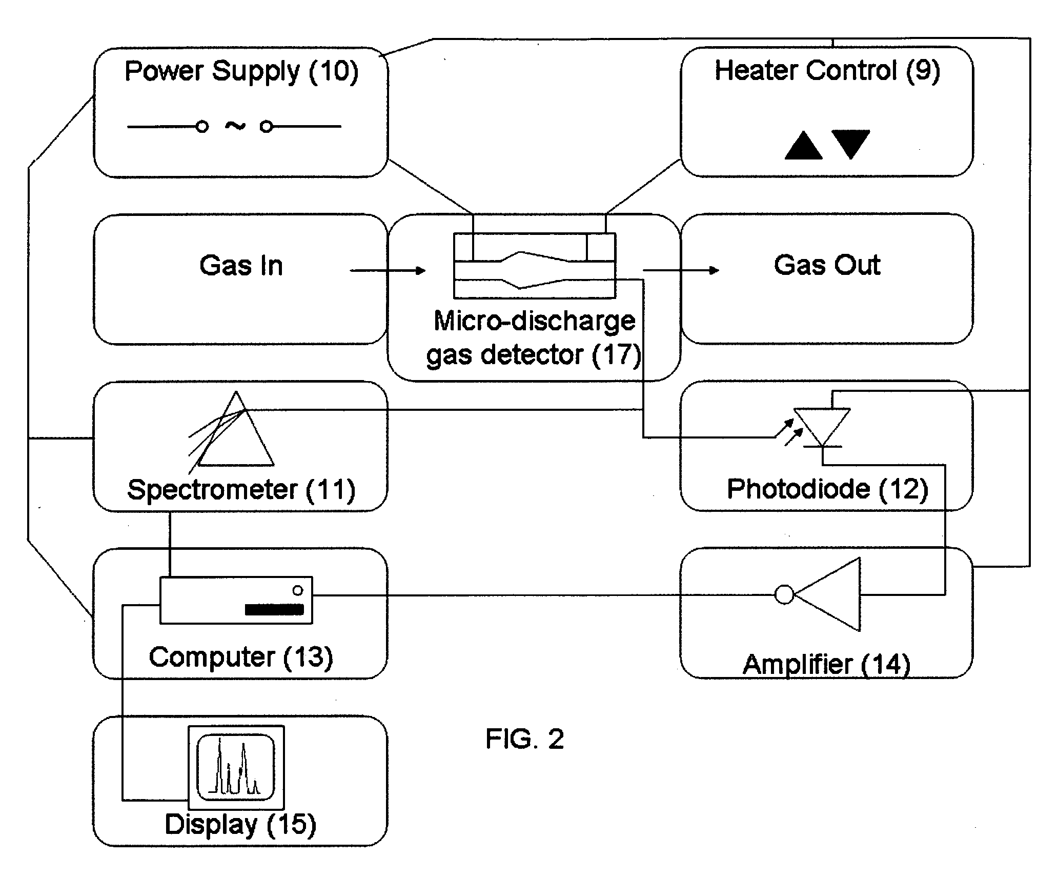
[0017]The gas detector of this invention is a capacitively coupled dielectric barrier discharge device, also called a micro-discharge gas detector (17, as shown in FIG. 2). In FIG. 1, the gas detector has an inner electrode 2 and an outer electrode 5, each made of hollow electrically conductive capillary tubing. The inner electrode 2 and outer electrode 5 are oriented coaxially. The inner electrode 2 and outer electrode 5 are separated longitudinally by a small gap as well as axially by a dielectric tube 4. An electric potential applied between the inner electrode 2 and outer electrode 5 creates an electrical discharge within a gas (also called a mixed gas composition, 20, as shown in FIG. 3)in the dielectric tube 4, at the gap (also called the discharge region 3) between the inner electrode 2 and the outer electrode 5. The discharge is characterized by the creation of a plasma. A plasma is electrically conductive due to the relatively high percentage of ions and electrons (electric...


PUM

PropertyMeasurementUnit
AC voltageaaaaaaaaaa
inner diameteraaaaaaaaaa
outer diameteraaaaaaaaaa

Abstract

A gas detector designed for use with a gas chromatography system, or alone, comprising a tubular inner electrode, a tubular outer electrode coaxial with the inner electrode, and a dielectric tube axially between the inner electrode and the outer electrode. The dielectric tube serves as a dielectric barrier between the inner electrode and the outer electrode. There is a longitudinal gap between the left end of the outer electrode and the right end of the inner electrode, and a sufficient voltage is applied across the gap between the electrodes to create an electrical discharge which emits light from a gas passing through the gap. The light is then detected and analyzed to determine the chemical constituents of the gas passing through the gap.

Description

FIELD OF THE INVENTION[0001]This invention relates to gas detectors. More particularly, this invention relates to dielectric barrier micro-discharge gas detectors and gas chromatograph detector systems.BACKGROUND OF THE INVENTION[0002]Gas chromatography is an analytical technique which entails the separation and often identification of individual compounds, or groups of compounds, within a mixture. A gas chromatography system takes a small sample of liquid or gas (typically about 0.1 cubic centimeter), and identifies the amounts of various compounds within the sample, often in the form of a chromatograph. A chromatograph is a line chart with the horizontal axis identifying different compounds and the vertical axis giving the concentration. The total amount of a compound in a given sample is usually related to the area under the peak associated with that particular compound. No other analytical technique is as powerful and as generally applicable as is gas chromatography. It is widel...

Claims


Application Information

Patent Timeline
Patent Type & Authority Applications(United States)
IPC IPC(8): G01N30/02
CPCG01N27/68G01N2030/025G01N30/74
Inventor KELLNER, DAVID G.CASTELEIN, MATTHEW A.
Owner CAVITON
Why Eureka
Try Eureka