Thermoelectric conversion module and method for manufacturing the same

Inactive Publication Date: 2009-02-05
MURATA MFG CO LTD
View PDF5 Cites 34 Cited by
  • Summary
  • Abstract
  • Description
  • Claims
  • Application Information

AI Technical Summary

Benefits of technology

[0027]The thermoelectric conversion module-manufacturing method enables the thermoelectric semiconductors, which correspond to such via-conductors, to be densely arranged in the laminate. Therefore, the thermoelectric conversion module can be readily manufactured so as to have a small size and high performance.
[0028]The wiring conductors and the thermoelectric conversion element pairs, as well as the multilayer circuit board, can be flexibly designed. Thus, the thermoelectric conversion module can be readily manufactured so as to h

Problems solved by technology

Thus, the element has relatively low thermoelectric conversion efficiency.
This prevents the thermoelec

Method used


Image

  • Thermoelectric conversion module and method for manufacturing the same
  • Thermoelectric conversion module and method for manufacturing the same
  • Thermoelectric conversion module and method for manufacturing the same

Examples


Example

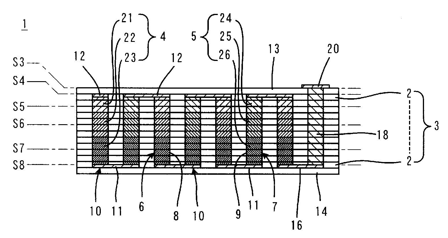
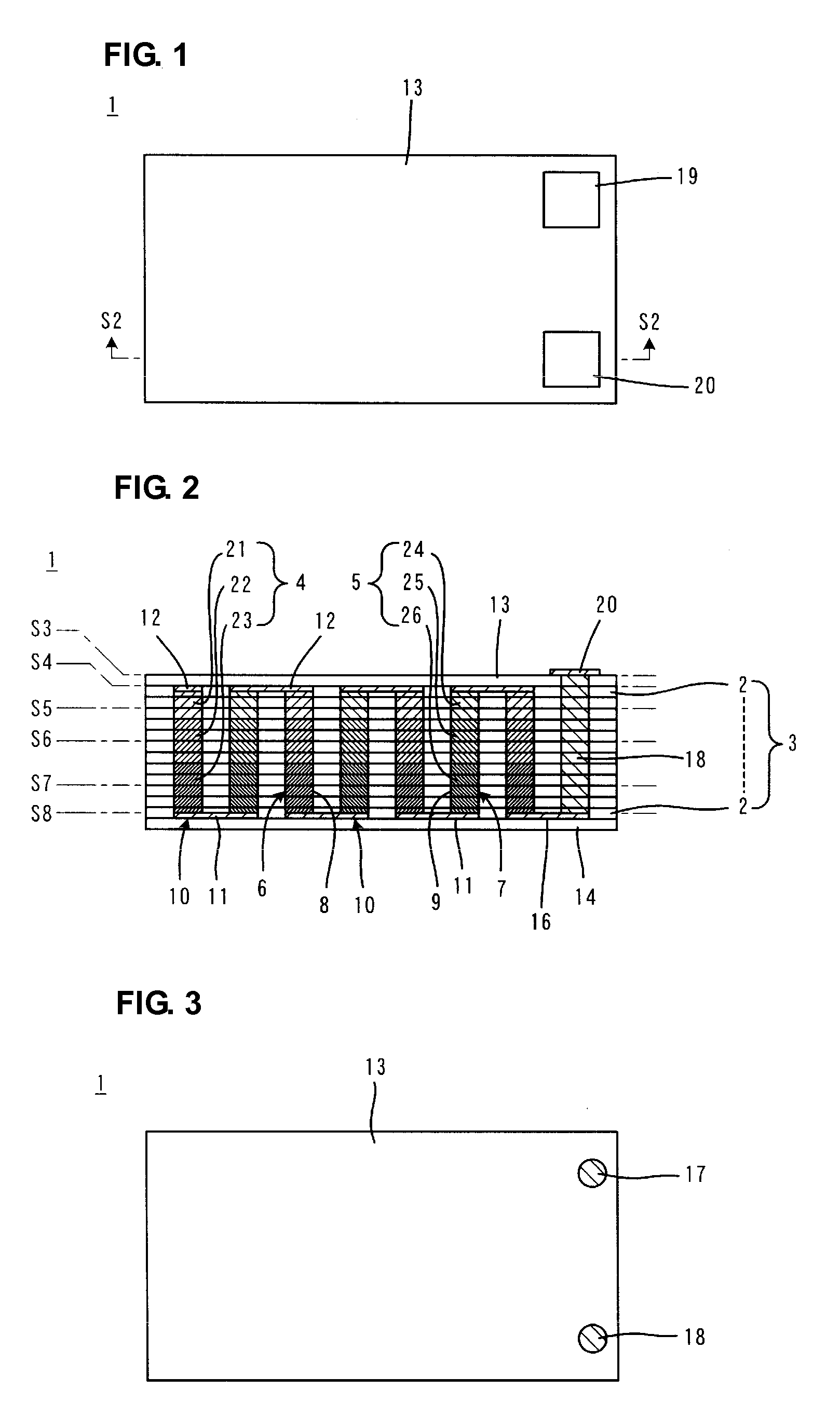
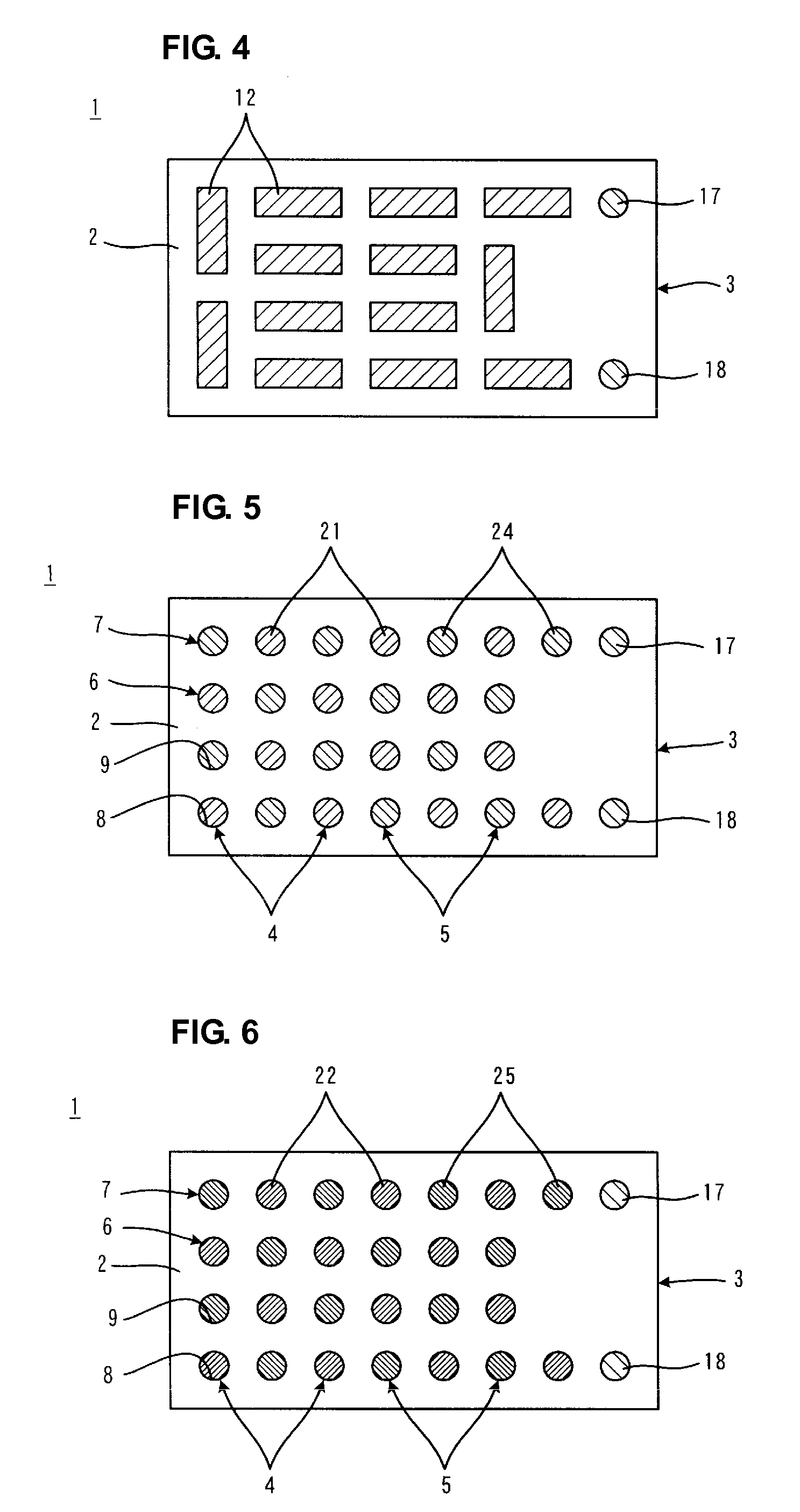
[0052]FIGS. 1 to 8 illustrate a thermoelectric conversion module 1 according to a first preferred embodiment of the present invention. FIG. 1 is a plan view of the thermoelectric conversion module 1. FIG. 2 is a sectional view taken along the line S2-S2 of FIG. 1. FIGS. 3 to 8 are sectional plan views taken along the lines S3 to S8, respectively, of FIG. 2.

[0053]The thermoelectric conversion module 1 includes a laminate 3 including a plurality of stacked insulating layers 2 which are electrically insulative. The insulating layers 2 are made of an alumina-based material, such as a BaO—Al2O3—SiO2 ceramic material or a ZnO—MgO—Al2O3—SiO2 glass material, for example. The thermoelectric conversion module 1 further includes a plurality of p-type thermoelectric semiconductors 4 and n-type thermoelectric semiconductors 5 arranged in the laminate 3. The p-type thermoelectric semiconductors 4 are made of, for example, Chromel. The n-type thermoelectric semiconductors 5 are made of, for exampl...


PUM


Abstract

A compact, high-performance thermoelectric conversion module includes a laminate having a plurality of insulating layers, p-type thermoelectric semiconductors and n-type thermoelectric semiconductors formed by a technique for manufacturing a multilayer circuit board, particularly a technique for forming a via-conductor. Pairs of the p-type thermoelectric semiconductors and the n-type thermoelectric semiconductors are electrically connected to each other in series through p-n connection conductors to define thermoelectric conversion element pairs. The thermoelectric conversion element pairs are connected in series through, for example, series wiring conductors. The thermoelectric semiconductors each have a plurality of portions in which the peak temperatures of thermoelectric figures of merit are different from each other. These portions are distributed in the stacking direction of the laminate.

Description

BACKGROUND OF THE INVENTION[0001]1. Field of the Invention[0002]The present invention relates to a thermoelectric conversion module and a method for manufacturing the thermoelectric conversion module, and more particularly, to an improvement in a method for manufacturing a compact, high-performance thermoelectric conversion module.[0003]2. Description of the Related Art[0004]Conventional techniques relating to the present invention are disclosed in Japanese Unexamined Patent Application Publication No. 8-153899 and Japanese Unexamined Patent Application Publication No. 8-222770.[0005]Japanese Unexamined Patent Application Publication No. 8-153899 discloses a thermoelectric conversion module including an insulating frame having a plurality of through-holes spaced from each other. The through-holes contain p-type or n-type compound semiconductor elements. The through-holes containing the p-type compound semiconductor elements and the through-holes containing the n-type compound semico...

Claims


Application Information

Patent Timeline
IPC IPC(8): H01L35/02H01L21/00
CPCH01L35/32H01L35/34H05K1/0206H05K2201/10219H05K3/4611H05K3/4629H05K1/0306H10N10/01H10N10/17
Inventor KAWAUCHI, YASUHIRONAKAMURA, TAKANORI
Owner MURATA MFG CO LTD
Why Eureka
Try Eureka