
Electric traction system for a vehicle having a dual winding ac traction motor

a technology of electric traction system and traction motor, which is applied in the direction of electric device control, battery/fuel cell control arrangement, dynamo-electric converter control, etc., can solve the problems of power usage and complexity of the various electrical systems of automobiles

Inactive Publication Date: 2009-02-05
GM GLOBAL TECH OPERATIONS LLC
View PDF13 Cites 74 Cited by
  • Summary
  • Abstract
  • Description
  • Claims
  • Application Information

AI Technical Summary

Benefits of technology

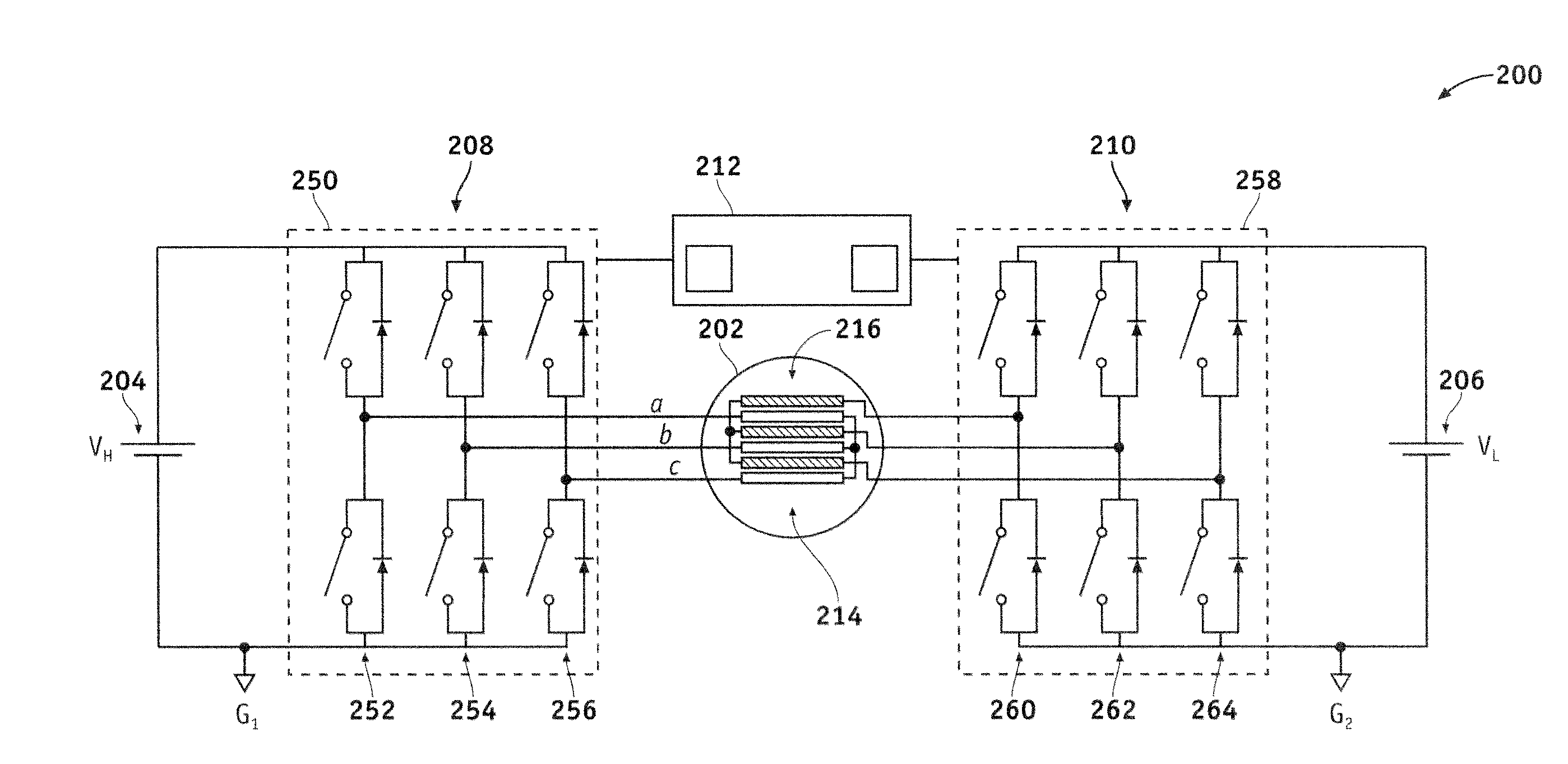
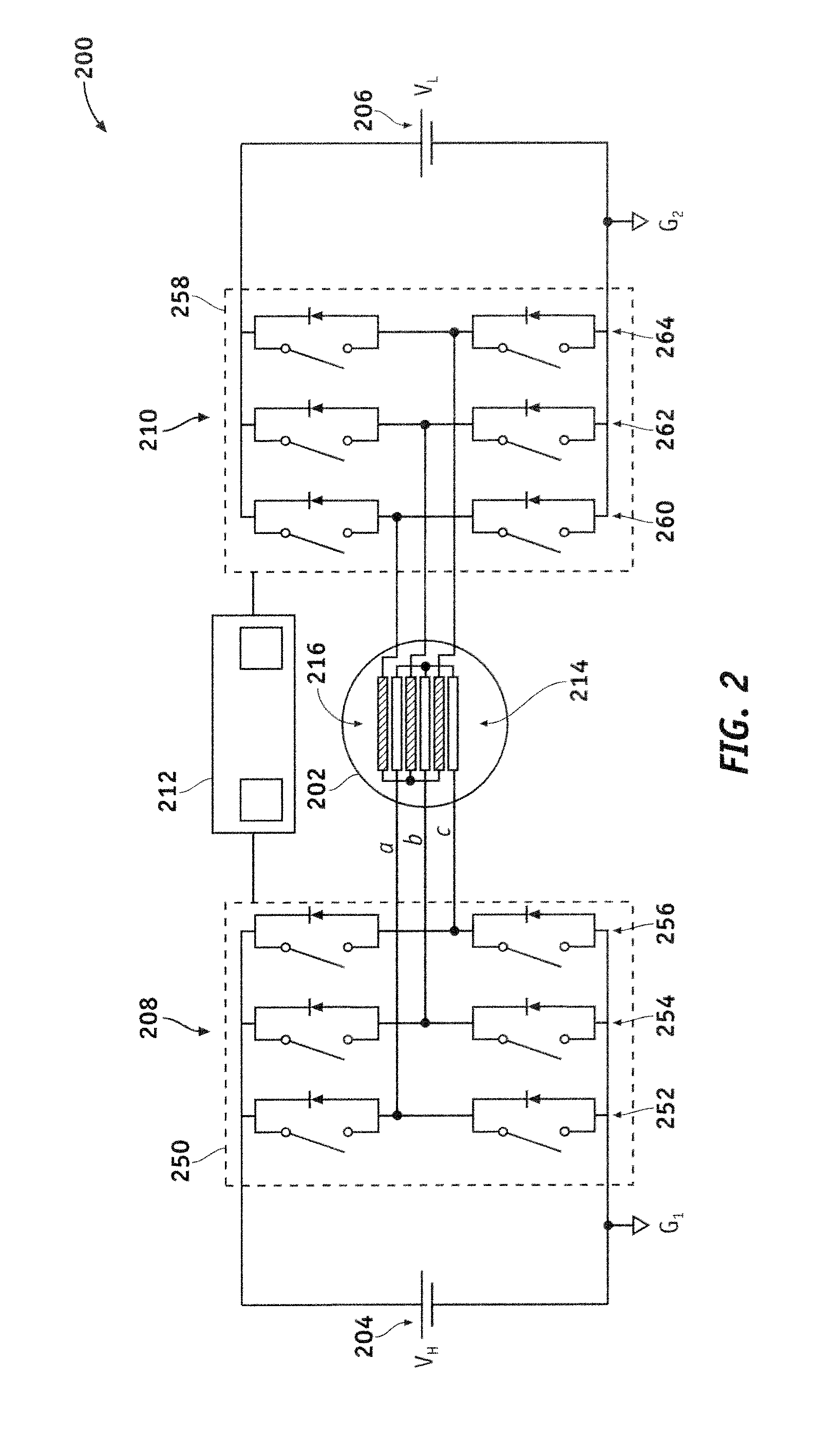
[0007]An electric traction system for a vehicle having a high voltage battery and a low voltage battery is also provided. The system includes an AC electric motor having a first set of windings and a second set of windings that occupy common stator slots of the AC electric motor, the first set of windings and the second set of windings being electrically isolated, and a double ended inverter system coupled to the AC electric motor. The double ended inverter system is configured to drive the AC electric motor using energy obtained from the high voltage battery and energy obtained from the low voltage battery. The double ended inverter system includes a first inverter subsystem coupled to the first set of windings and to the high voltage battery, and a second inverter subsystem coupled to the second set of windings and to the low voltage battery.
[0008]An electric traction system for a vehicle having a first energy source with a relatively high nominal DC voltage, and a second energy source with a relatively low nominal DC voltage is also provided. This system includes an AC electric motor having a first set of windings and a second set of windings. The first set of windings is electrically isolated from the second set of windings, and the first set of windings and the second set of windings occupy common stator slots of the AC electric motor to form a transformer for voltage matching between the first energy source and the second energy source. The electric traction system also utilizes a first inverter subsystem coupled to the first energy source and to the first set of windings, and a second inverter subsystem coupled to the second energy source and to the second set of windings. The first and second inverters subsystems are adapted to drive the AC electric motor (individually or collectively). The electric traction system employs a controller coupled to the first inverter subsystem and to the second inverter subsystem. The controller is configured to control the first inverter subsystem and the second inverter subsystem to achieve desired power flow between the first energy source, the second energy source, and the AC electric motor.
[0009]This summary is provided to introduce a selection of concepts in a simplified form that are further described below in the detailed description. This summary is not intended to identify key features or essential features of the claimed subject matter, nor is it intended to be used as an aid in determining the scope of the claimed subject matter.

Problems solved by technology

One of the changes involves the power usage and complexity of the various electrical systems within automobiles, particularly alternative fuel vehicles, such as hybrid, electric, and fuel cell vehicles.
However, the power sources (e.g., batteries) used in such applications provide only direct current (DC) power.

Method used


Image

  • Electric traction system for a vehicle having a dual winding ac traction motor
  • Electric traction system for a vehicle having a dual winding ac traction motor
  • Electric traction system for a vehicle having a dual winding ac traction motor

Examples


Embodiment Construction

[0015]The following detailed description is merely illustrative in nature and is not intended to limit the embodiments of the subject matter or the application and uses of such embodiments. As used herein, the word “exemplary” means “serving as an example, instance, or illustration.” Any implementation described herein as exemplary is not necessarily to be construed as preferred or advantageous over other implementations. Furthermore, there is no intention to be bound by any expressed or implied theory presented in the preceding technical field, background, brief summary or the following detailed description.

[0016]Techniques and technologies may be described herein in terms of functional and / or logical block components, and with reference to symbolic representations of operations, processing tasks, and functions that may be performed by various computing components or devices. For the sake of brevity, conventional techniques related to inverters, AC motor control, electric and hybri...


PUM


Abstract

An electric traction system for a vehicle having a high voltage battery and a low voltage battery is provided. The system includes an AC electric motor and a double ended inverter system coupled to the AC electric motor. The AC electric motor has a first set of windings and a second set of windings that occupy common stator slots, where the first set of windings and the second set of windings are electrically isolated from each other. The double ended inverter system drives the AC electric motor using energy obtained from the high voltage battery and energy obtained from the low voltage battery. The double ended inverter system utilizes a first inverter subsystem coupled between the first set of windings and the high voltage battery, and a second inverter subsystem coupled between the second set of windings and the low voltage battery.

Description

CROSS-REFERENCE TO RELATED APPLICATION(S)[0001]This application claims the benefit of U.S. provisional patent application Ser. No. 60 / 952,742, filed Jul. 30, 2007 (the entire content of which is incorporated by reference herein).TECHNICAL FIELD[0002]Embodiments of the subject matter described herein relate generally to an electric traction system. More particularly, embodiments of the subject matter relate to methods and apparatus for matching different battery voltages using a double ended inverter coupled to a dual winding AC traction motor.BACKGROUND[0003]In recent years, advances in technology, as well as ever evolving tastes in style, have led to substantial changes in the design of automobiles. One of the changes involves the power usage and complexity of the various electrical systems within automobiles, particularly alternative fuel vehicles, such as hybrid, electric, and fuel cell vehicles.[0004]Many of the electrical components, including the electric motors used in electr...

Claims


Application Information

Patent Timeline
Patent Type & Authority Applications(United States)
IPC IPC(8): H02P27/06H02J7/14
CPCB60L11/1868Y02T10/7005Y02T10/7066Y02T90/34Y02T10/641B60L2220/54B60L2220/58Y02T10/644B60L15/00B60L58/20Y02T10/64Y02T10/70Y02T90/40
Inventor NAGASHIMA, JAMES M.WELCHKO, BRIAN A.JOHN, GEORGECHAKRABARTI, SIBAPRASADPERISIC, MILUNSMITH, GREGORY S.
Owner GM GLOBAL TECH OPERATIONS LLC
Learn More