Jig for detecting postion

Active Publication Date: 2009-02-05
TOKYO ELECTRON LTD
View PDF9 Cites 9 Cited by
  • Summary
  • Abstract
  • Description
  • Claims
  • Application Information

AI Technical Summary

Benefits of technology

[0021]In accordance with the present disclosure, it is possible to load the position detecting jig even into the apparatu

Problems solved by technology

However, in case that the wafer is not transferred to a preset position in each apparatus, the delivery of the wafer or processing of the wafer may not be performed properly, for example.
For this reason, as for an apparatus ha

Method used


Image

  • Jig for detecting postion
  • Jig for detecting postion
  • Jig for detecting postion

Examples


Embodiment Construction

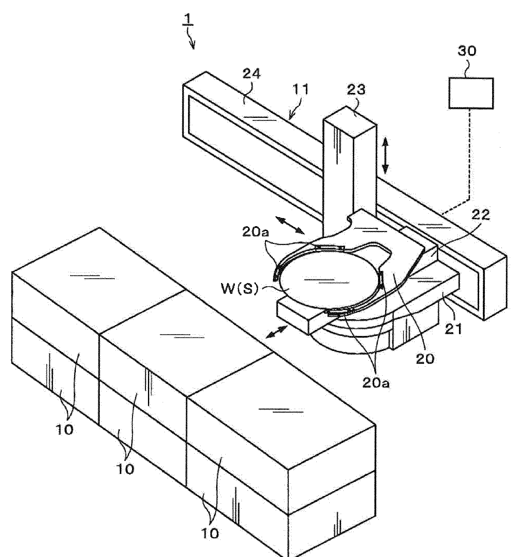
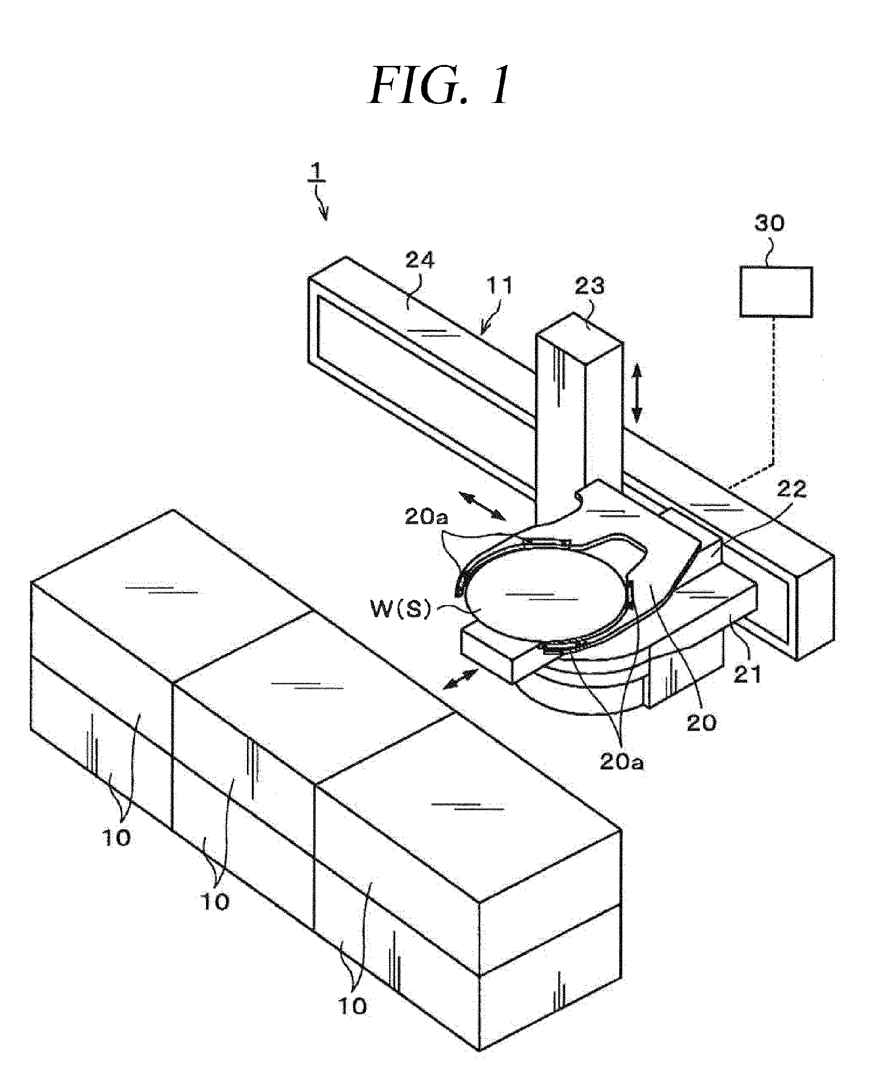
[0035]Hereinafter, an embodiment of the present invention will be described in detail with reference to the accompanying drawings. FIG. 1 provides a schematic configuration view of a substrate processing system 1 to which a position detecting wafer is applied as a position detecting jig in accordance with the embodiment of the present invention.

[0036]For example, the substrate processing system 1 includes a plurality of processing apparatuses 10 for processing a wafer W and a transfer mechanism 11 for transferring the wafer W to the processing apparatuses 10.

[0037]For example, the transfer mechanism 11 has a transfer arm 20. The transfer arm 20 has a front end substantially having, for example, a C shape. A plurality of supporting portions 20a is installed at inner portions of the C-shaped part of the transfer arm 20, and the wafer W can be sustained on these supporting portions 20a. The transfer arm 20, for example, can move back and forth along a rail 22 installed on a base 21. Fo...


PUM


Abstract

A position alignment of a transfer point of a transfer arm is performed by using a position detecting wafer capable of being loaded into an apparatus having a thin transfer port. The position detecting wafer S includes an electrostatic capacitance detecting sensor 50 for detecting an electrostatic capacitance in relation with a reference object for the position alignment. The electrostatic capacitance detecting sensor 50 includes a plurality of electrostatic capacitance detecting electrodes 52, each forming the electrostatic capacitance in relation with the reference object; and a control circuit 51 for controlling a detection of the electrostatic capacitance by each electrostatic capacitance detecting electrode 52, while communicating with each electrostatic capacitance detecting electrode 52. The electrostatic capacitance detecting electrodes 52 are provided on a rear surface of the position detecting wafer S, and the control circuit 51 is provided on a front surface of the position detecting wafer S.

Description


Claims


Application Information

Patent Timeline
Owner TOKYO ELECTRON LTD
Why Eureka
Try Eureka