Method of Monitoring and/or Controlling or Automatically Controlling the Voltage of at Least One Group of Cells in a Compound of Cells of an Energy Storage Device

a technology of energy storage device and cell compound, which is applied in the direction of secondary cell servicing/maintenance, electrochemical generator, transportation and packaging, etc., can solve the problems of increased wiring expenditure, inability to control, and increased susceptibility to faults, so as to prevent the destruction or damage of individual cell groups

Active Publication Date: 2009-02-05
BAYERISCHE MOTOREN WERKE AG
View PDF23 Cites 10 Cited by
  • Summary
  • Abstract
  • Description
  • Claims
  • Application Information

AI Technical Summary

Benefits of technology

[0013]Thus in comparison to the known state of the art, the method according to the invention, the cell group logic according to the invention and the central logic according to the invention have the advantage that the rail line can be used for supplying the cell group logic with a reference voltage by way of which the cell group logic can also be supplied with power, as well as for a data communication between the central logic and the cell group logic without interfering with the reference voltage. According to the invention, this takes place in that the data communication takes place by means of voltage levels which are above the maximal voltage level, up to which the cell group logic exchanges energy with the rail line for charging or discharging the cell group; that is, up to which the rail line is used for “transmitting” the reference voltage. When the maximal voltage level is exceeded, the cell group logic no longer exchanges energy with the rail line for charging or discharging the cell group connected therewith, and the voltage applied to the rail line is no longer used as reference voltage for the charging or discharging of the cell groups or the individual cells; that is, the supply line, by way of which the cell group is connected with the cell group logic, is definitely separated from the rail line. As a result, the charging or discharging of the group of cells is carried out by means of an unadulterated reference voltage and, during the data communication, the charging or discharging of the group of cells is interrupted in order to exclude a faulty charging or discharging.
[0014]The cell group logic is advantageously switched to active when a rail voltage is applied to the rail line which is above an enable voltage level situated below the maximal voltage level. The cell group logic is therefore advantageously constructed such that the voltage comparator unit switches the cell group logic to active when a rail voltage is applied to the rail line which is above an enable voltage level situated below the maximal voltage level. The central logic therefore advantageously has a control unit which drives the voltage converter unit to impress a rail voltage which is above an enable voltage level situated below the maximal voltage level in order to switch the cell group logic to active. In this advantageous embodiment, the cell group logics are compulsorily switched to passive, that is, disabled, in the event of a “short circuit to ground” fault. In this manner, a destruction of or damage to the individual cell groups is prevented.

Problems solved by technology

However, this data line results in increased wiring expenditures and therefore in an increased susceptibility to faults.
However, because of the resulting voltage level difference especially in the sphere of monitoring the voltage of individual cells at a cell compound, such an approach is unsuitable because measuring results or reference voltage levels impressed onto the supply lines, which are used for charging or discharging the cell groups or individual cells, are hereby falsified.
However, since also here the data signals to be transmitted are simply superimposed on the quiescent voltage of the data transmission line in the form of current pulses which, even in the case of a small quantity, because of the high (output) resistance of the generator, result in strong voltage pulses, which are therefore easily detectable on the receiver side and which, on the receiver side, can easily be demodulated in a reliable manner by a comparator or a window comparator, it is also not possible here to carry out a power supply, which simultaneously defines a reference voltage level, by way of the data transmission line used for the data transmission and the power supply.
Thus, by means of the existing methods and systems for the data transmission on supply lines, no reliable monitoring and / or controlling or automatic controlling of the voltage of individual cells in a cell compound of an energy storage device, particularly of an energy storage device in an onboard power supply system of a motor vehicle, can be carried out where the voltage is determined for each group of cells and the group of cells is charged and / or discharged as a function of the determined voltage, at which voltage each group of cells is connected with a cell group logic, and by way of each group of cells, the cell group voltage is determined and, in the cell group logic, is compared with a desired voltage applied to a direct-voltage line with respect to the ground, and the group of cells is charged and / or discharged as a function of the difference between the determined cell group voltage and the desired voltage by way of the direct-voltage line, because the desired voltage would be falsified because of the data transmission.

Method used


Image

  • Method of Monitoring and/or Controlling or Automatically Controlling the Voltage of at Least One Group of Cells in a Compound of Cells of an Energy Storage Device
  • Method of Monitoring and/or Controlling or Automatically Controlling the Voltage of at Least One Group of Cells in a Compound of Cells of an Energy Storage Device
  • Method of Monitoring and/or Controlling or Automatically Controlling the Voltage of at Least One Group of Cells in a Compound of Cells of an Energy Storage Device

Examples


Embodiment Construction

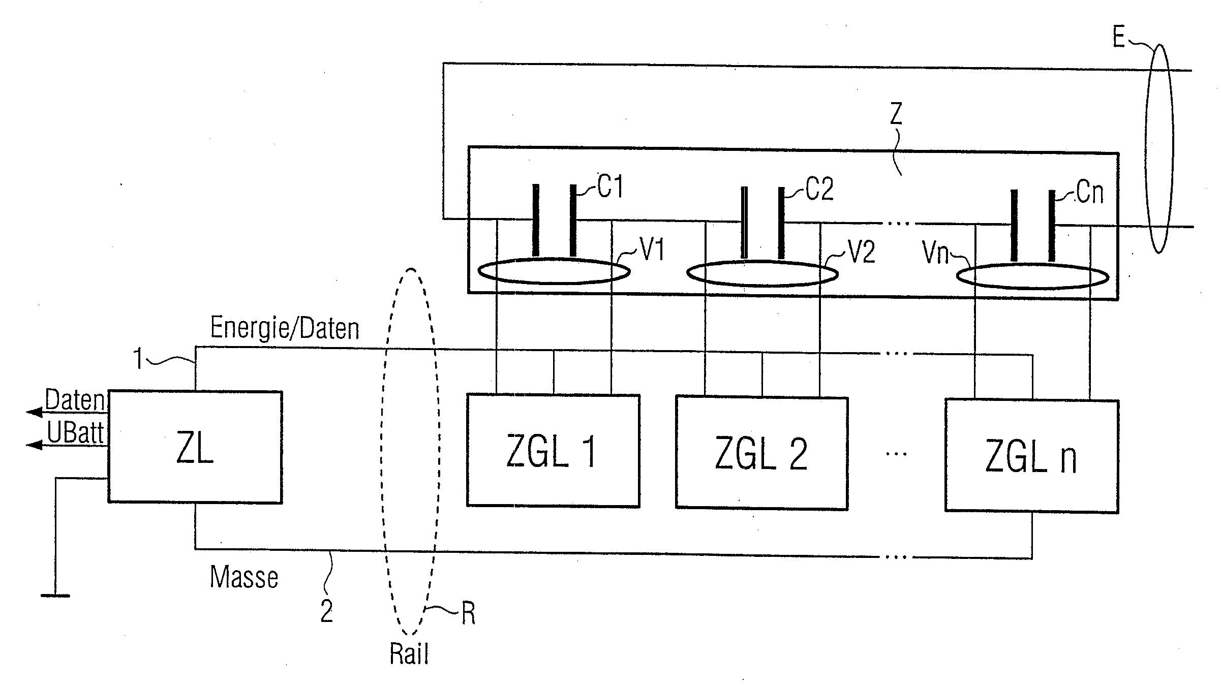
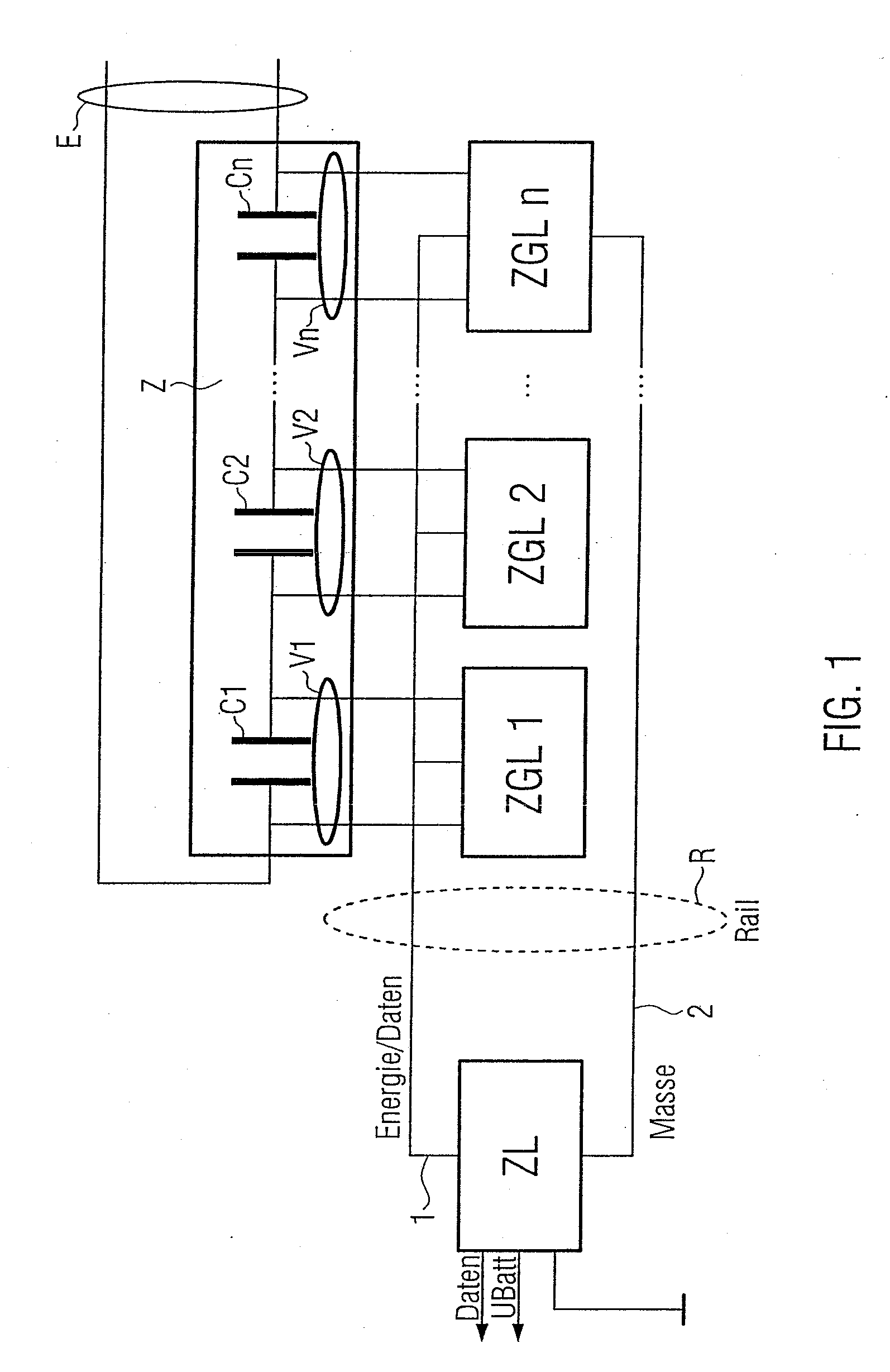
[0032]FIG. 1 illustrates a preferred embodiment of the physico-technical construction of the system for implementing the method according to the invention. The system is implemented, for example, in a vehicle not shown here. In FIG. 1, several cells C1, C2, . . . Cn are connected in series in a cell compound Z. The cell compound Z is connected to the onboard energy supply system E of the vehicle and is used for providing energy, mainly in the case of hybrid vehicles. The cells C1 to Cn advantageously are double-layer capacitors. Each cell C1 to Cn of the cell compound Z is connected with a respective cell group logic ZGL1, ZGL2, . . . , SGLn.

[0033]In FIG. 1, the system is further developed such that each cell C1 to Cn forms a group of cells which is connected with its own cell group logic. The cell group logics ZGL1, ZGL2, . . . , ZGLn are connected with a rail line R which has a conductor 1 for energy / data and a grounding conductor 2. The rail line R is connected with a higher-rank...


PUM


Abstract

Thus, according to the invention, for monitoring and/or controlling or automatically controlling the voltage of at least one group of cells in a cell compound of an energy storage device, particularly an energy storage device in an onboard power supply system of a motor vehicle, a data communication is carried out between a central logic and a cell group logic by way of the rail line connecting the latter, in which case voltage levels exist between an idle level situated at or above a maximal voltage level, up to which the cell group logic exchanges energy with the rail line for charging or discharging the cell group, and a data level situated above the idle level.

Description

[0001]This application is a continuation of PCT International Application No. PCT / EP2007 / 000972, filed on Feb. 5, 2007, which claims priority under 35 U.S.C. § 119 to German Application No. 10 2006 005 334.6, filed Feb. 7, 2006, the entire disclosures of which are expressly incorporated by reference herein.BACKGROUND AND SUMMARY OF THE INVENTION[0002]The invention relates to a method of monitoring and / or controlling or automatically controlling the voltage of at least one group of cells in a compound of cells of an energy storage device, which consists of a series connection of the individual cells of the energy storage device, in which case an individual cell may consist of one cell or of parallel-connected cells. In particular, the invention relates to a compound of cells of an energy storage device in an onboard power supply system of a motor vehicle. The invention further relates to a cell group logic for monitoring and / or controlling or automatically controlling the voltage of ...

Claims


Application Information

Patent Timeline
Patent Type & Authority Applications(United States)
IPC IPC(8): H01G9/00B60R16/00
CPCH02J7/0022H02J13/0003H04B3/548Y04S40/146H04B2203/547Y02B90/2692H04B2203/5412H02J7/0014H02J13/00002Y04S10/30Y02E60/00Y02B90/20Y04S40/121
Inventor FROESCHL, JOACHIMSCHARNER, SEBASTIAN
Owner BAYERISCHE MOTOREN WERKE AG
Why Eureka
Try Eureka