
Hot-Gas-Ducting Housing Element, Protective Shaft Jacket and Gas Turbine System

a technology of hot gas-ducting housing and protective shaft jacket, which is applied in the direction of machines/engines, liquid fuel engines, light and heating apparatus, etc., can solve the problems of limited number of starts, maximum number of starts of gas turbine systems, and the number of starts after which an inspection for cracking or repair is to be performed, so as to reduce the risk of cracking and increase the number of starts before inspection or repair.

Inactive Publication Date: 2009-02-05
SIEMENS AG
View PDF8 Cites 12 Cited by
  • Summary
  • Abstract
  • Description
  • Claims
  • Application Information

AI Technical Summary

Benefits of technology

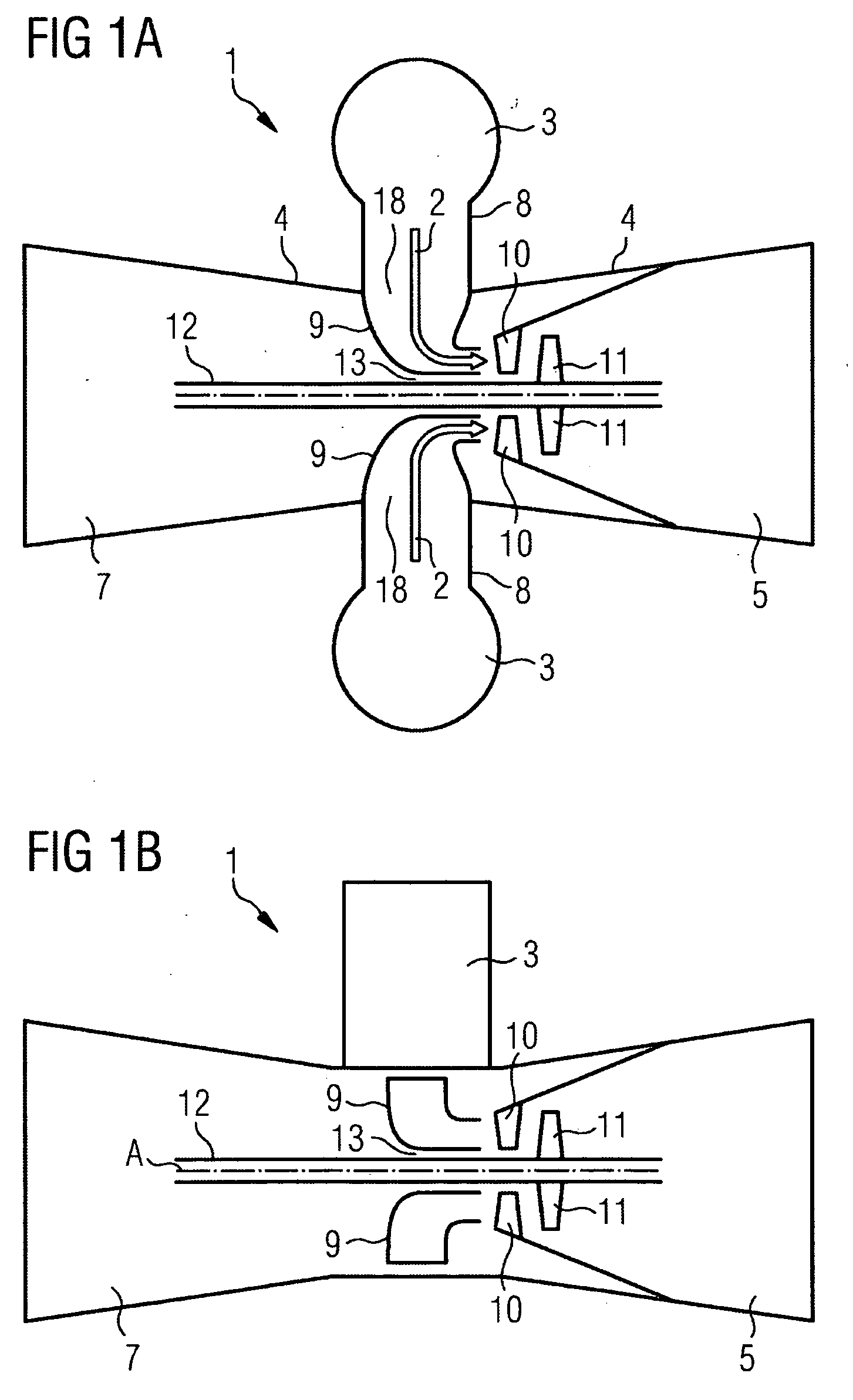
[0010]Compared with said prior art an object of the present invention is to provide an improved hot-gas-ducting housing element for a hot-gas-ducting housing of a gas turbine system, in which element the risk of cracking is reduced and the number of starts before an inspection or repair can be increased.
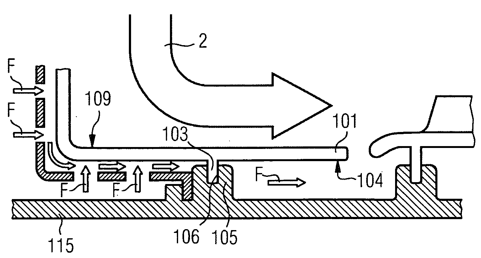
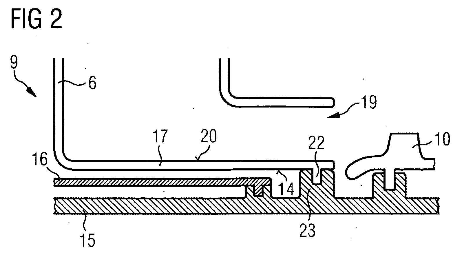
[0017]Arranging the rib in the region of the inner housing hub's circumferential surface bordering the opening on the turbine side will enable a cooling fluid to flow largely unimpeded along the inner housing hub up to the opening on the turbine side, which alone will improve the possibilities for cooling the inner housing hub. As a result of the inventive arrangement of the cooling fluid channels it is now also possible to improve the cooling possibility in the rib region by reducing the barrier effect of the rib or improving the ducting of the cooling fluid in the region of the rib.
[0018]The barrier effect on the flow of the cooling fluid can be reduced if the rib is provided with cooling fluid channels enabling the cooling fluid to pass through the rib. The flow of the cooling fluid will therein be especially little impeded if said cooling fluid channels are arranged in the rib such that they run close to the circumferential surface of the inner housing hub virtually parallel to its axial direction.
[0019]The cooling effect can also be improved if the inner housing hub is provided with cooling fluid channels. They can each have, for example, an opening on the protective shaft jacket side, meaning an opening in the circumferential surface requiring to be arranged facing the protective shaft jacket, and an opening on the hot gas side, meaning an opening in the surface ducting the hot gas. In particular a cooling fluid film can form on the surface, on the hot gas side, of the inner housing hub if, over their course through the inner housing hub as viewed from the opening on the protective shaft jacket side constituting an inlet orifice for the cooling fluid, the cooling fluid channels have an inclination in the flow direction of the hot gas requiring to be ducted.
[0020]Additionally or alternatively to the cooling fluid channels provided with openings on the protective shaft jacket side and hot gas side there can also be cooling fluid channels running parallel to the hot-gas-ducting surface of the inner housing hub between an inlet orifice for the cooling fluid to enter and an outlet orifice for the cooling fluid to exit. Cooling fluid channels of said type will enable particularly effective cooling of the inner housing hub.
[0021]A hot-gas-ducting surface and in particular the inner housing hub can be provided with a thermally insulating and / or corrosion-inhibiting and / or oxidation-inhibiting coating in order to minimize wear and tear in the hot-gas-ducting housing.

Problems solved by technology

To reduce the risk of a defect due to cracking, the maximum number of starts, meaning the number of starts of the gas turbine system after which an inspection for cracking or a repair is to be performed, is generally limited.

Method used


Image

  • Hot-Gas-Ducting Housing Element, Protective Shaft Jacket and Gas Turbine System
  • Hot-Gas-Ducting Housing Element, Protective Shaft Jacket and Gas Turbine System
  • Hot-Gas-Ducting Housing Element, Protective Shaft Jacket and Gas Turbine System

Examples


first embodiment

[0049]A first embodiment variant of the hot-gas-ducting housing element 6 is shown in FIG. 4. The figure shows the inner housing hub 17a of the radiation guard 16a as well as the protective shaft jacket 15a in the region of the stud 23a. The stud 23a of the protective shaft jacket 15a shown in FIG. 4 differs from the stud 23 of the protective shaft jacket 15 shown in FIG. 3 in being embodied wider and not projecting so far beyond the surface 20a of the protective shaft jacket 15a. Nor does it have a passage hole for the passage of a cooling fluid. A passage opening in the form of a drilled hole 25a enabling the cooling fluid to pass through the rib 22a is instead arranged in the rib 22a of the inner housing hub 17a. The passage hole is arranged in the immediate vicinity of the circumferential surface 14a, of the inner housing hub 17a, facing the protective shaft jacket 15a. Corresponding passage holes are distributed spaced apart in the circumferential direction over the entire annu...

third embodiment

[0052]the hot-gas-ducting housing element 6 is shown in FIG. 6. The figure shows the inner housing hub 17c, the radiation guard 16 and the protective shaft jacket 15 in the region of the stud 23. As in FIG. 5, the inner housing hub 17c has passage openings in the form of drilled holes 28c. Said drilled holes 28c each have an opening 29c on the protective shaft jacket side and an opening 30c located in the front side of the inner housing hub 17c. Between the opening 29c on the protective shaft jacket side and the opening 30c on the front side, each passage hole 28c runs mostly parallel to the hot-gas-ducting surface 20c of the inner housing hub 17c.

[0053]Cooling fluid F entering through the opening 29c on the protective shaft jacket side is guided in the region of the rib 22c by means of the drilled holes 28c through the interior of the inner housing hub 17c and thereby causes cooling of the inner housing hub 17c before exiting from the opening 30c on the front side.

[0054]In the emb...


PUM


Abstract

Disclosed is a hot-gas-conducting housing element for a hot-gas-conducting housing of a gas turbine system encompassing a compressor, a turbine, and a turbine rotor. The hot gas-conducting housing element is embodied so as to surround a protective shaft jacket placed around the turbine rotor and conduct a hot gas to the turbine. The hot gas-conducting housing element comprises: —at least one hot gas inlet; —an opening facing the turbine; —a section for conducting the hot gas from the at least one hot gas inlet to the opening facing the turbine, said conducting section being provided with an inner housing hub which is configured so as to surround the protective surface facing the protective shaft jacket. Said rib extends in the circumferential direction, protrudes from the circumferential surface, and is disposed in the zone of the circumferential surface bordering the opening that faces the turbine. The rib and / or the inner housing hub is / are fitted with cooling fluid ducts.

Description

CROSS REFERENCE TO RELATED APPLICATIONS[0001]This application is the US National Stage of International Application No. PCT / EP2006 / 063825, filed Jul. 4, 2006 and claims the benefit thereof. The International Application claims the benefits of European application No. 05015001.0 filed Jul. 11, 2005, both of the applications are incorporated by reference herein in their entirety.FIELD OF INVENTION[0002]The present invention relates to a hot-gas-ducting housing element for a hot-gas-ducting housing, which element can be arranged particularly in a gas turbine system around a turbine rotor of the gas turbine system and serves to conduct a hot gas to a turbine part of the gas turbine system. The present invention relates further to a protective shaft jacket of the hot-gas-ducting housing, which jacket is embodied for surrounding the turbine rotor of the gas turbine system. The present invention relates finally to the hot-gas-ducting housing itself and to a gas turbine system having a hot-...

Claims


Application Information

Patent Timeline
Patent Type & Authority Applications(United States)
IPC IPC(8): F02C7/18F01D11/08
CPCF01D5/08F01D25/12F01D25/14F05D2260/202F23R2900/03044F05D2250/231F05D2260/201F23R3/60
Inventor BOHRENKAMPER, GERHARDSCHMAHL, MILAN
Owner SIEMENS AG
Learn More