
Fuel cell system

a fuel cell and system technology, applied in the field of fuel cell systems, can solve the problems of inability to accurately detect the variation of pressure, pressure sensor may have difficulty in measuring the quantity of pressure decrease of hydrogen, etc., and achieve the effect of high-precision detection of hydrogen leakag

Inactive Publication Date: 2009-02-05
TOYOTA JIDOSHA KK
View PDF6 Cites 29 Cited by
  • Summary
  • Abstract
  • Description
  • Claims
  • Application Information

AI Technical Summary

Benefits of technology

[0008]The fuel cell system of the invention detects the occurrence of a hydrogen leakage after the pressure regulator is opened to keep the hydrogen supply flow path in the state with no pressure regulation. Even when a hydrogen leakage occurs on the opposite side of the state quantity measurement unit across the pressure regulator, the fuel cell system of the invention can accurately detect a pressure variation or a flow rate variation accompanied with the hydrogen leakage. The fuel cell system of this arrangement enables highly accurate detection of the occurrence of a hydrogen leakage.
[0028]Even when the hydrogen in the downstream of the pressure regulator has a high pressure, the fuel cell system having either of these mechanisms reduces the pressure of the hydrogen to open the pressure regulator.
[0032]Even after the closure of the shutoff valve, hydrogen is continuously supplied from the buffer tank into the hydrogen supply flow path. The fuel cell system of this arrangement extends the time usable for detection of a hydrogen leakage and accordingly enhances the accuracy of leakage detection.
[0034]The fuel cell system of this arrangement uses the state quantity measurement unit located between the two pressure regulators to detect a hydrogen leakage from the shutoff valve. The state quantity measurement unit provided in this location is not required to have a very high pressure resistance. A sensor having a high measurement accuracy is thus applicable to the state quantity measurement unit to accurately detect a hydrogen leakage from the shutoff valve.
[0036]The fuel cell system of the invention equalizes the pressure level in the upstream of the pressure regulator with the pressure level in the downstream of the pressure regulator. Even when a hydrogen leakage occurs on the opposite side of the state quantity measurement unit across the pressure regulator, the pressure variation or the flow rate variation accompanied with the hydrogen leakage is immediately transmitted to the state quantity measurement unit. The fuel cell system of this arrangement thus enables highly accurate detection of the occurrence of a hydrogen leakage.

Problems solved by technology

In the occurrence of a hydrogen leakage at a specific position, the pressure sensor may have difficulty in measuring the quantity of pressure decrease of hydrogen.
In this case, the pressure regulator interferes with transmission of a pressure variation accompanied with the hydrogen leakage occurring in the downstream of the pressure regulator.
The pressure sensor located in the upstream of the pressure regulator is thus unable to accurately detect the pressure variation.

Method used


Image

  • Fuel cell system
  • Fuel cell system
  • Fuel cell system

Examples


first embodiment

A. First Embodiment

(A1) General Configuration of Fuel Cell System

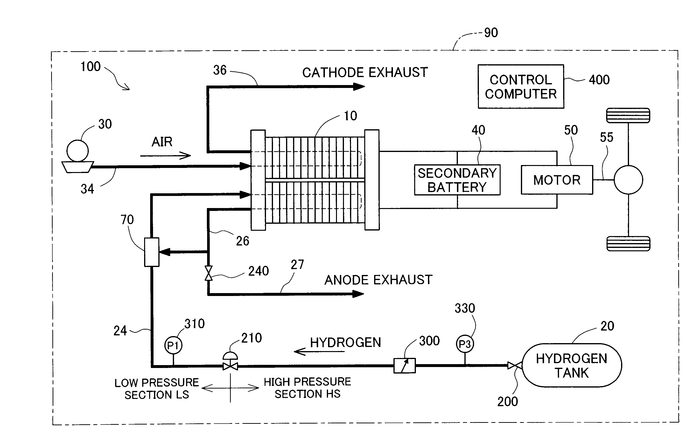
[0062]FIG. 1 schematically illustrates the general configuration of a fuel cell system 100 in a first embodiment of the invention. As illustrated, the fuel cell system 100 of the embodiment is mounted on a vehicle 90 and includes fuel cells 10 that generate electric power through electrochemical reaction of hydrogen and oxygen, a hydrogen tank 20 that stores high-pressure hydrogen gas, an air compressor 30 that feeds the air to the fuel cells 10, a secondary battery 40 that is charged with the electric power generated by the fuel cells 10, a motor 50 that drives an axle 55 with the electric power generated by the fuel cells 10 and the electric power discharged from the secondary battery 40, and a control computer 400 that controls the operations of the fuel cell system 100 and the vehicle 90.

[0063]The fuel cells 10 are polymer electrolyte fuel cells and have a stack structure as a lamination of multiple unit cells (not...

first modified example

[0096]In the structure of the first embodiment, the pressure regulator 210 has the fixed set pressure and the automatically unadjustable opening. In a first modified example of the first embodiment, a variable pressure regulator is adopted for the pressure regulator 210 and has an opening automatically adjustable under control of the control computer 400.

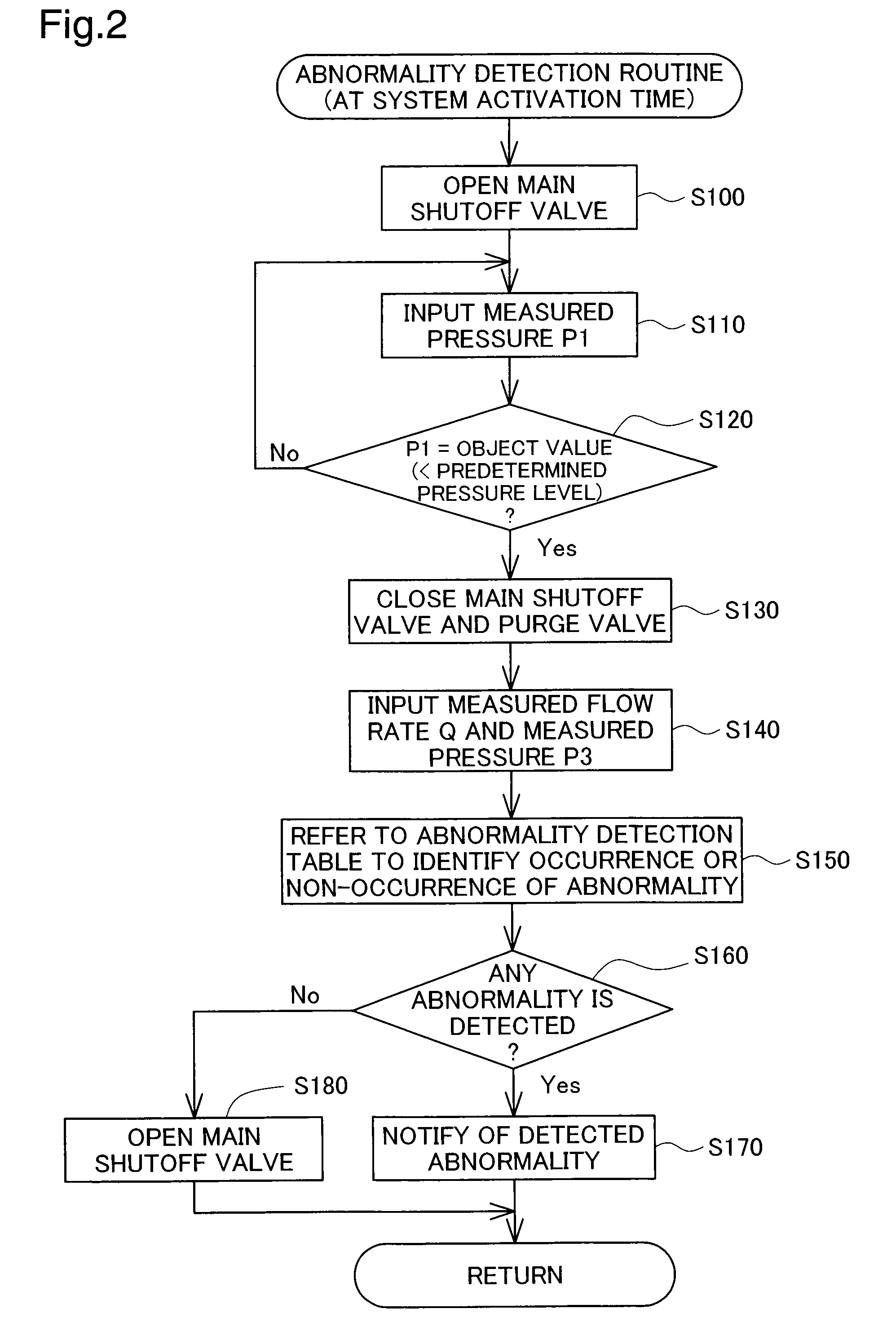
[0097]FIG. 6 is a flowchart showing an abnormality detection routine in the first modified example with the variable pressure regulator as the pressure regulator 210. This abnormality detection routine is performed in the system stop state. In the abnormality detection routine of FIG. 6, the control computer 400 first closes the main shutoff valve 200 and the purge valve 240 (step S500) to shut off the flow path connected to the anodes of the fuel cells 10. The control computer 400 subsequently forces the variable pressure regulator to be fully opened (step S510).

[0098]The control computer 400 inputs the pressure P1 measured in the ...

second modified example

[0101]FIG. 7 schematically illustrates the general configuration of a fuel cell system 100b in a second modified example. The fuel cell system 100b of the second modified example shown in FIG. 7 has a similar structure to that of the fuel cell system 100 of the first embodiment shown in FIG. 1 but additionally includes a buffer tank 21 located between the main shutoff valve 200 and the hydrogen flowmeter 300 in the hydrogen supply flow path 24. The buffer tank 21 temporarily stores hydrogen gas supplied from the hydrogen tank 20 into the hydrogen supply flow path 24.

[0102]In the course of abnormality detection in the closed state of the main shutoff valve 200 and the purge valve 240, the hydrogen gas temporarily stored in the buffer tank 21 is supplied to the hydrogen supply flow path 24 connected with the buffer tank 21. This arrangement extends the time usable for detection of a hydrogen leakage and thus desirably enhances the accuracy of leakage detection.


PUM


Abstract

In a fuel cell system of the invention, a hydrogen leakage detection process closes a shutoff valve, which shuts off a supply of hydrogen from a hydrogen supply unit into a hydrogen supply flow path, and opens a pressure regulator, which reduces a pressure of hydrogen in the hydrogen supply flow path, so as to keep the hydrogen supply flow path in a state with no pressure regulation and make the fuel cell system in a leakage detectable state. In this leakage detectable state, the hydrogen leakage detection process measures at least one of a pressure and a flow rate as a state quantity of hydrogen in the hydrogen supply flow path that feeds the supply of hydrogen to fuel cells. The hydrogen leakage detection process analyzes a detected behavior of the state quantity in the leakage detectable process and specifies the occurrence of a hydrogen leakage in the downstream of the hydrogen supply unit. This arrangement enables highly accurate detection of a hydrogen leakage in the fuel cell system with the pressure regulator provided in the hydrogen supply flow path.

Description

TECHNICAL FIELD[0001]The present invention relates to a fuel cell system. More specifically the invention pertains to a technique of detecting a leakage of hydrogen gas supplied to fuel cells.BACKGROUND ART[0002]In a fuel cell system that generates electricity with supplies of hydrogen and oxygen to fuel cells, various techniques of detecting a leakage of hydrogen supplied to anodes of the fuel cells have been proposed to enhance the safety of the fuel cell system.[0003]One proposed technique of leakage detection disclosed in JP-A-2003-148252 estimates a quantity of pressure decrease in a hydrogen supply flow path from a total quantity of hydrogen as the sum of the quantity of hydrogen consumed for power generation by the fuel cells and the quantity of unconsumed hydrogen discharged from the fuel cells. The leakage detection technique then compares the estimated quantity of pressure decrease with an actual quantity of pressure decrease measured by a pressure sensor and detects the o...

Claims


Application Information

Patent Timeline
IPC IPC(8): H01M8/04
CPCH01M8/04089H01M8/04388H01M8/04679Y02E60/50H01M16/006H01M2250/20Y02T90/32H01M8/04753Y02T90/40Y02E60/10
Inventor SUEMATSU, KEIGOYOKOYAMA, TATSUAKIKATANO, KOJITOMOSADA, NOBUHIRO
Owner TOYOTA JIDOSHA KK
Learn More