

Apparatus for head acupressure using air pressure
- Summary
- Abstract
- Description
- Claims
- Application Information
AI Technical Summary
Benefits of technology
Problems solved by technology
Method used
Image

Examples
Embodiment Construction
[0014]Reference will now be made in detail to the preferred embodiment of the present invention with reference to the attached drawings.
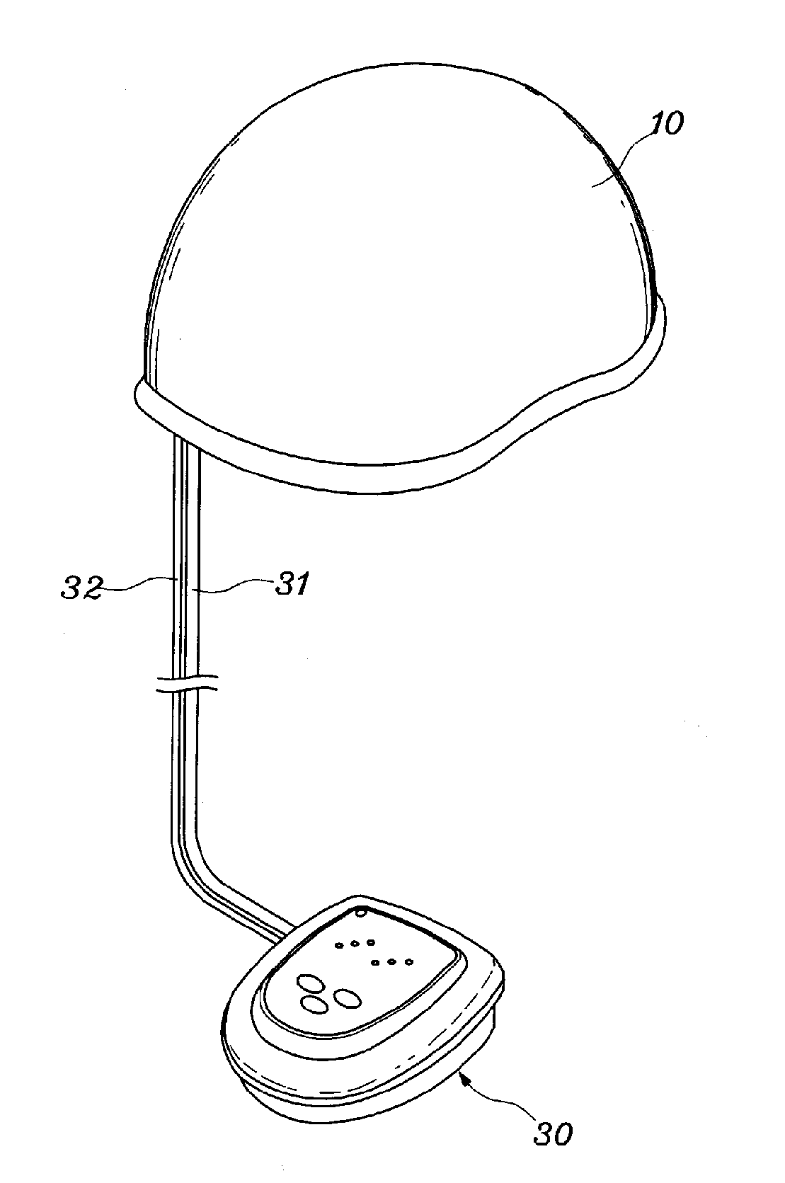
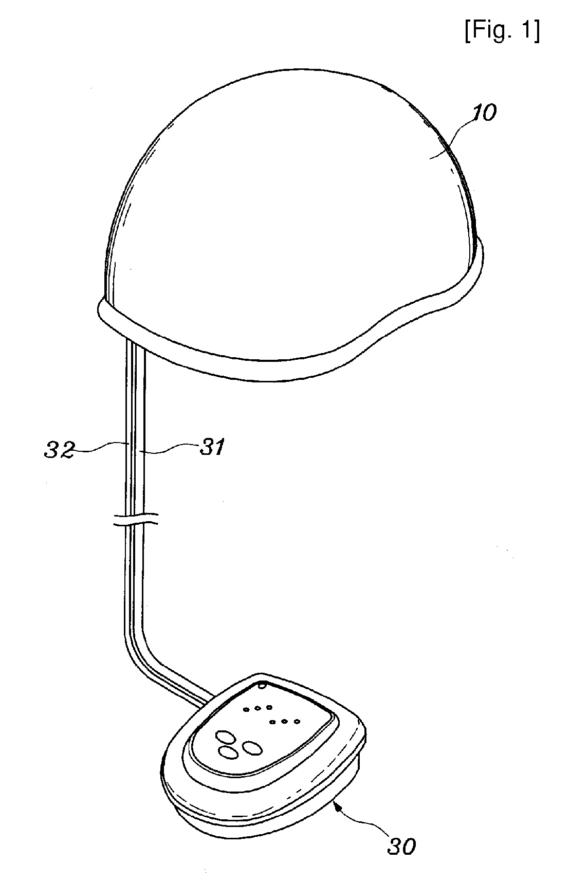
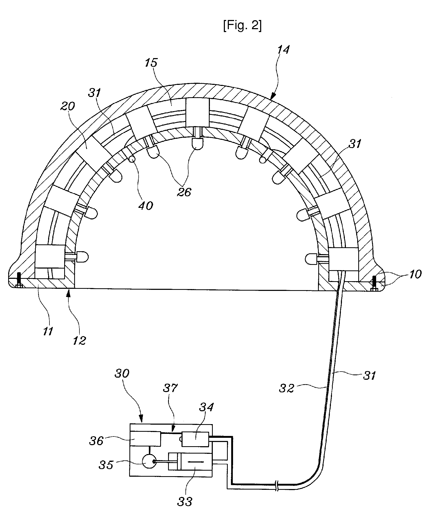
[0015]As shown in FIG. 1, a pneumatic scalp acupressure apparatus according to the present invention comprises a helmet 10, a plurality of pneumatic cylinder units 20 (not shown in FIG. 1) mounted radially inside the helmet 10, and a pneumatic pressure generator 30 interconnected to the plurality of pneumatic cylinder units 20 through a pneumatic tube 31 so as to generate air pressure to supply the generated air pressure to the inside of the cylindrical cylinder units. In FIG. 1, reference numeral 32 not illustrated denotes an electric wire.
[0016]First, as shown in FIG. 2, the helmet 10 is constructed of a double structure having an inner shell 12 and an outer shell 14. The inner shell 12 is formed in a hemispherical shape and has an outwardly extending flange 11 formed at a lower end thereof in such a fashion as to extend outwardly from a periphera...
PUM
 Abstract
Description
Claims
Application Information