Instrument For Inserting Intraocular Lens

a technology for intraocular lenses and instruments, which is applied in the field of intraocular lens insertion devices, can solve problems such as yielding operation errors, and achieve the effects of improving reliability of operation, facilitating handling, and simplifying structur

Active Publication Date: 2009-02-05
HOYA CORP
View PDF102 Cites 81 Cited by
  • Summary
  • Abstract
  • Description
  • Claims
  • Application Information

AI Technical Summary

Benefits of technology

[0024]According to the intraocular lens insertion device as set forth in the first aspect of the invention, the slider is moved by handling the operating part, and then the intraocular lens is discharged by the plunger. Accordingly, the push-out operation of the intraocular lens can be performed securely and safely, with a simpler structure. According to the intraocular lens insertion device as set forth in the second aspect of the invention, the slider can be moved by pinching the operating part with fingers from both sides, and thus reliability of the operation can be improved.
[0025]According to the intraocular lens insertion device as set forth in the third aspect of the invention, the slider can be moved by one hand, thus enabling more easier handling.
[0026]According to the intraocular lens insertion device as set forth in the fourth aspect of the invention, the intraocular lens can be folded in a predetermined direction, thus preventing operation troubles, ensuring even more reliable insertion of the intraocular lens.
[0027]According to the intraocular lens insertion device as set forth in the fifth aspect of the invention, the optic part of the intraocular lens is pressed down only at the time of use, and the lens holding part does not press down the optic part of the lens in an intact state, and thus permanent deformation of an elastic material can be suppressed even after a long period of preservation.
[0028]According to the intraocular lens insertion device as set forth in the sixth aspect of the invention, one surface of the intraocular lens moved to the transition portion can be pressed down with a simple structure. Further, since the lens holding part is urged toward the sidewall of the main body, there is a further advantage in terms of assembly process that the intraocular lens can be placed on a lens placement portion easily.
[0029]According to the intraocular lens insertion device as set forth in the seventh aspect of the invention, the slider is provided with the inserting passage, and thus the discharge of the intraocular lens can be ensured, by preventing the axial misalignment of the plunger.

Problems solved by technology

However, in the above patent documents 1 or 2, it is necessary to move the lens from the stationary position to a position where it can be pushed out during its use, and there is a fear of yielding operational mistake accompanying the movement operation.

Method used


Image

  • Instrument For Inserting Intraocular Lens
  • Instrument For Inserting Intraocular Lens
  • Instrument For Inserting Intraocular Lens

Examples


first embodiment

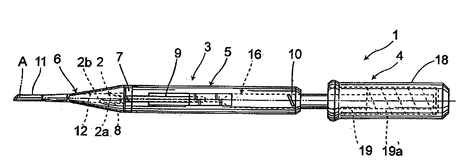
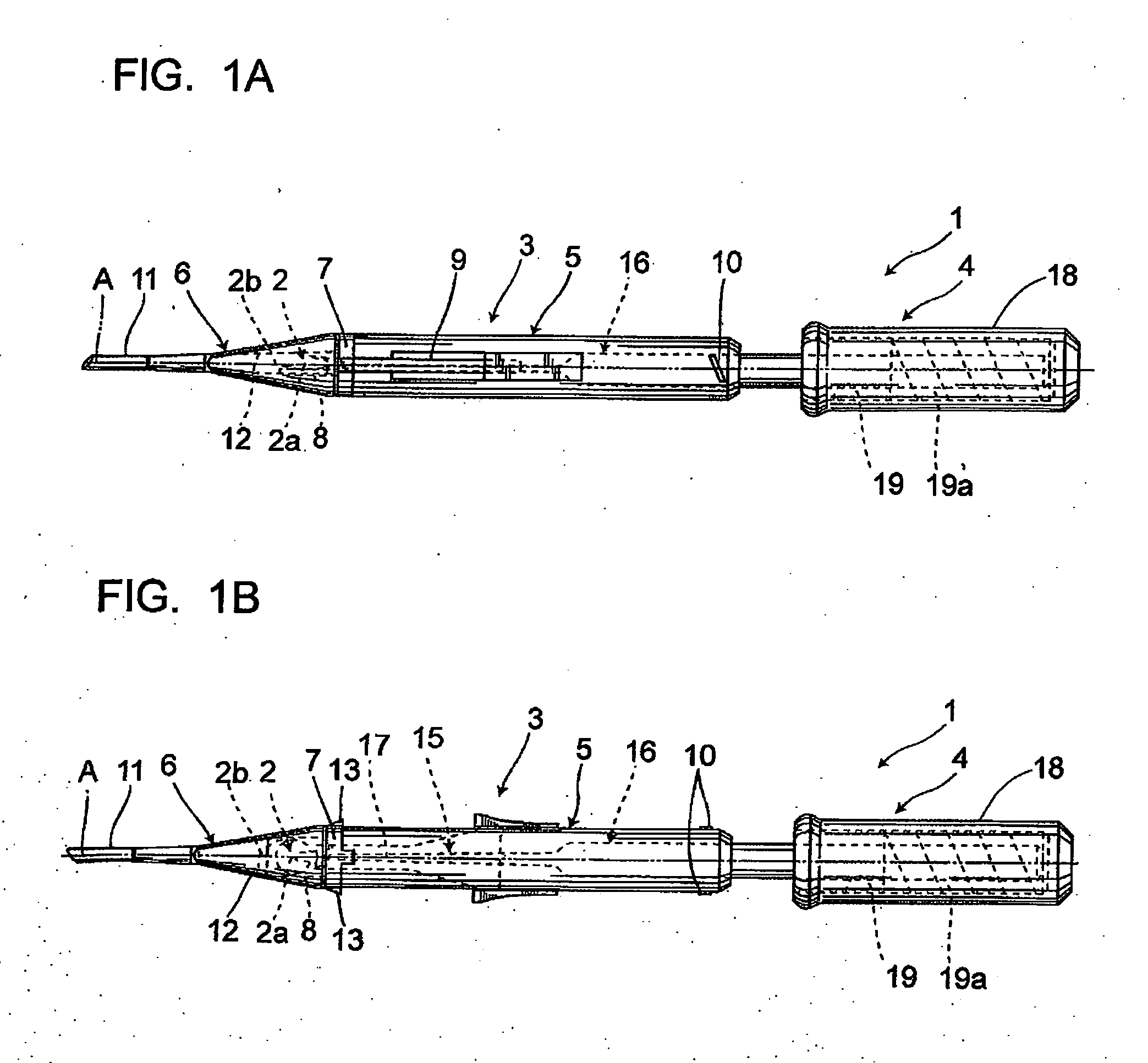
[0048]First, a first embodiment of the present invention is explained. An intraocular lens insertion device 1 shown in FIG. 1 is used to safely and quickly discharge into an eye a deformable intraocular lens 2 (hereinafter referred to as “lens 2”), and more particularly is a preset type intraocular lens insertion device 1 having the lens 2 preset in the intraocular lens insertion device 1. More specifically, the intraocular lens insertion device 1 is provided with a main body 3 that places the lens 2 therein and then inserts the lens 2 into an eye, and a lens push-out mechanism 4 that pushes out the lens 2 placed in the lens placement portion. In the meantime, for the lens 2 illustrated in the present embodiment is employed one comprising an optic part 2a and loop parts 2b.

[0049]Said main body 3 comprises a cylindrical proximal member 5 and a distal member 6 that is tapered relative to the proximal member 5. This proximal member 5 and the distal member 6 are detachably integrated w...

second embodiment

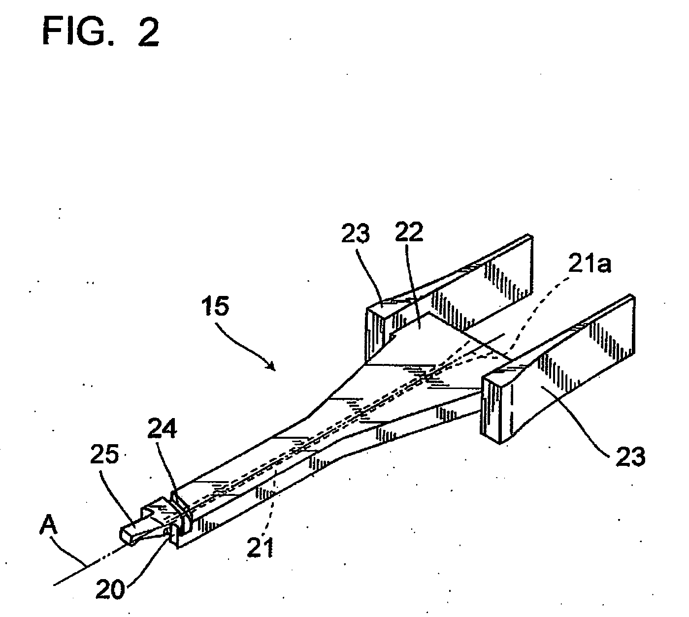
[0080]Next, a second embodiment of the present invention will be explained. The same portions as those described in the above-mentioned structure will be designated by the same reference numerals, and the duplicate description thereof will be omitted. Specifically, the intraocular lens insertion devices of the first and second embodiments are common in the sense that they comprise the main body 3 for placing the lens 2 and inserting the lens 2 into an eye; and the lens push-out mechanism 4 that pushes out the lens 2 placed in said lens placement portion 8, while the second embodiment differs from the first embodiment only in that it comprises a lock mechanism 30.

[0081]The lock mechanism 30 locks the plunger 16, and is capable of being unlocked only when the slider 15 is pushed out. The lock mechanism 30 comprises a lock member 31 provided in a detachable manner and a lock reception portion 32 provided in the plunger 16.

[0082]As shown in FIG. 6, the lock member 31 comprises a locking...

third embodiment

[0087]Next, a third embodiment of the present invention will be explained. The same portions as those described in the above-mentioned structure will be designated by the same reference numerals, and the duplicate description thereof will be omitted. Specifically, the intraocular lens insertion device of the third embodiment is the same as the ones of the foregoing embodiments in that it comprises the main body 3 for placing the lens 2 and inserting the lens. 2 into an eye; and the lens push-out mechanism 4 that pushes out the lens 2 placed in said lens placement portion 8, except the structure of the lock mechanism 30 described in the second embodiment.

[0088]The lock mechanism 30 serves to locks the plunger 16, and is capable of being unlocked in association with the operation for pushing out the slider 15. This lock mechanism 30 comprises an engagement portion 40 provided in the slider 15, an engagement hole 41 for engagement with the engagement portion 40, and a disk part 42 prov...


PUM


Abstract

An intraocular lens insertion device for inserting an intraocular lens capable of securely and safely pushing out the lens by a simple structure. An intraocular lens insertion device (1) comprises: a main body (3) having a lens placement portion (8) on which the lens (2) with a pair of loop parts (2b) at its optic part (2a) is placed, a transition portion (12) deforming the lens (2), and a nozzle portion (11) discharging the lens (2); and a lens push-out mechanism (4) pushing out the lens (2) placed on the lens placement portion (8). The lens push-out mechanism (4) comprises a plunger (16) pushing out the lens (2) and a slider (15) having a lens contact part (20) larger than the plunger (16). The slider (15) comprises an operating part (23) projected to the outside of the body (3).

Description

TECHNICAL FIELD[0001]The present invention relates to an intraocular lens insertion device that inserts an intraocular lens into an aphakic eye after a cataract operation, or, to an intraocular lens insertion device that inserts a phakic intraocular lens during a refractive surgery.BACKGROUND ART[0002]In cataract operations, removing an opacified lens by phacoemulsification (PEA) and implanting an intraocular lens after an opacified lens has been removed are widely performed. The types of intraocular lens include a hard intraocular lens with its optic area made of a hard material, such as PMMA, and a soft intraocular lens made of a soft material such as silicone elastomer or soft acrylic. When using a hard intraocular lens, the intraocular lens must be inserted through an incision in the cornea or sclera that is formed so as to have about the same width as the diameter of the optic area. On the other hand, when using a soft intraocular lens, folding of the optic area allows the intr...

Claims


Application Information

Patent Timeline
Patent Type & Authority Applications(United States)
IPC IPC(8): A61F9/007
CPCA61F2/167A61F2/1678
Inventor ICHINOHE, TAKASHIKUDOH, KAZUNORI
Owner HOYA CORP
Why Eureka
Try Eureka