
Cold forming process for manufacturing ball pivots

a technology of ball pivots and forming processes, which is applied in the direction of manufacturing tools, mechanical equipment, rotary machine parts, etc., can solve the problems of generating cost-intensive and time-consuming operations, reducing the need for manufacturing costs, and requiring the purchase of waste materials as a first semi-finished produ

Inactive Publication Date: 2009-02-12
ZF FRIEDRICHSHAFEN AG
View PDF1 Cites 8 Cited by
  • Summary
  • Abstract
  • Description
  • Claims
  • Application Information

AI Technical Summary

Benefits of technology

[0006]The object of the present invention is to provide a process for manufacturing ball pivots with a ball area, a cone area and a thread area, in which the number of pieces per unit of time for manufacturing individual ball pivots can be substantially reduced, so that the necessary manufacturing costs can be significantly reduced.
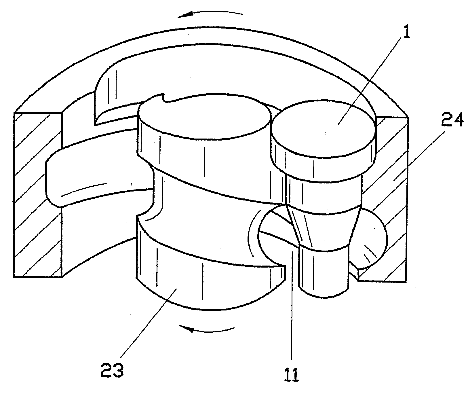
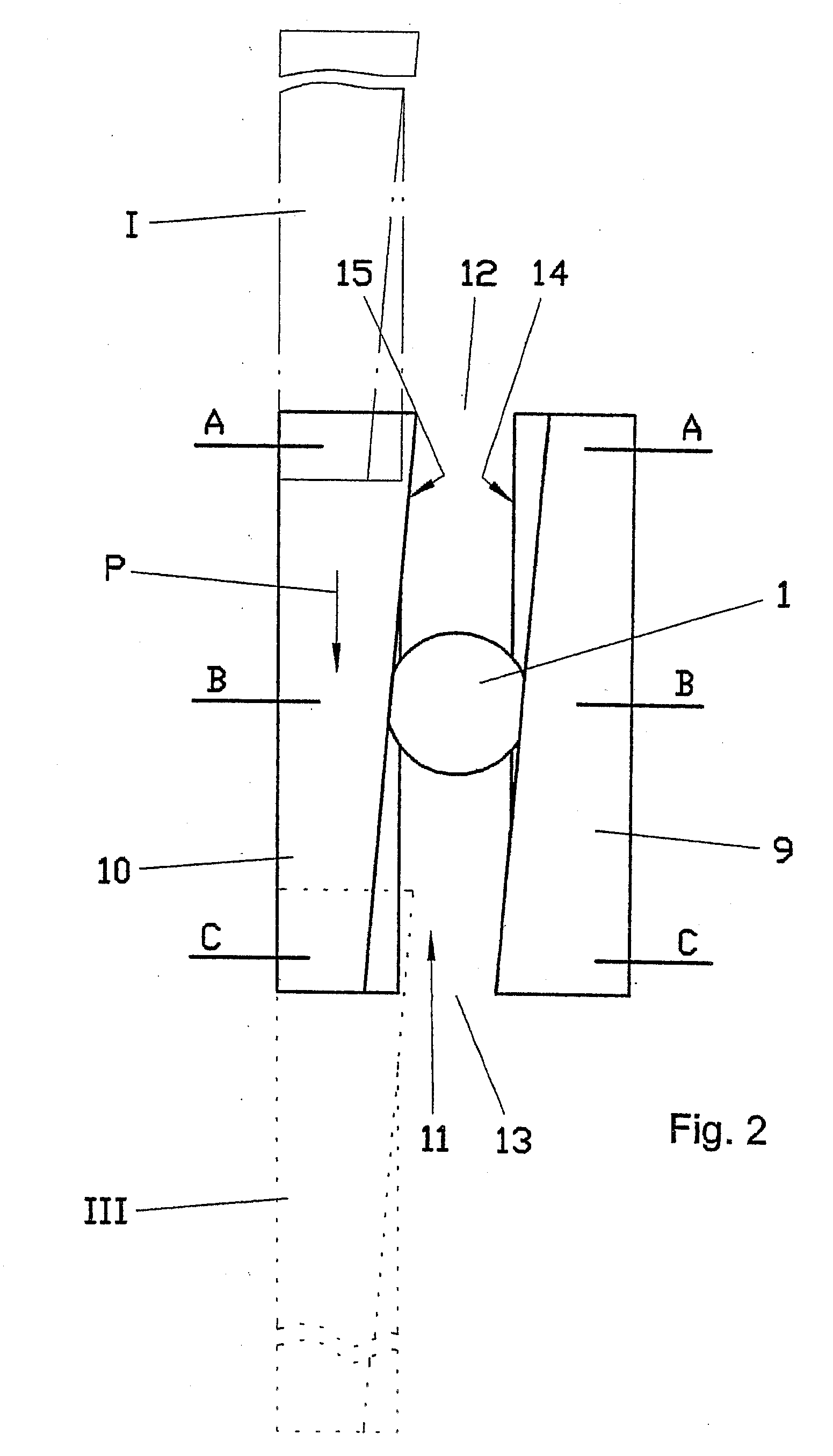
[0010]Due to the combination of the manufacturing operations, it is thus possible to manufacture a considerably greater number of ball pivots than has hitherto been known from the state of the art. This becomes possible, among other things, due to the fact that a plurality of functional areas, for example, the ball area, the cone area and the thread area, can be machined simultaneously by a tool during flat jaw rolling or round-jaw rolling. Moreover, the disposal of any waste material, which is absolutely necessary in case of manufacture by machining, is obviously eliminated.
[0011]Since the investment for a rolling machine is in the same cost range as for purchasing a lathe, the new inventive solution also leads to cost advantages in the area of the initial investment for manufacturing ball pivots due to the higher output of workpieces.
[0012]Moreover, it proved to advantageous in the process according to the present invention to form at first a neck area between the cone area and the cylindrical area intended for forming the ball during the flat-jaw or round-jaw rolling. Examples of strength measurements on ball pivots manufactured according to the novel process have revealed that the fatigue strength of the ball pivots can be increased by up to 50% by forming a neck area by rolling. Due to the increase in the fatigue strength by rolling a neck, it also becomes possible to use steels with microalloying elements, whose purchase price is substantially lower than that of the heat-treatable steels necessary for heat treatments. The cold forming of the C—Mn steels alloyed with microalloying elements is sufficient especially in the neck area to reach a sufficient strength. The increase in the strength values can be used to reduce the overall size of corresponding ball pivots at equal external loads.
[0013]Furthermore, it proved to be expedient as another special embodiment of the process according to the present invention that a blind hole-like recess, which is open on the front side, is pressed before the rolling operation into the free end of the ball pivot blank, which free end is intended for forming the ball area. The blind hole-like recess may be formed by the upper die used for pressing. The recess facilitates the forming of the cylindrical partial area of the ball pivot intended for forming the ball area to its final spherical shape. In addition, the recess does, of course, represent saving of material. If the blind hole-like recess, the so-called pole hole, is still present at least partly after the manufacture of the ball area of the ball pivot, the recess may be used, for example, to receive sensors or used as a grease reservoir. Closing the pole hole, for example, by means of a plastic cover is, of course, also conceivable in this connection.

Problems solved by technology

In addition, there is a disadvantage that the waste material must first be purchased as a semifinished product.
In addition, it is disadvantageous that cycle times that would substantially exceed a number of 10 pieces per minute are not possible on the machine tools that are commonly used at present.
Thus, cost-intensive and time-consuming operations are generated until the ball pivot is manufactured in case of non-machining forming of the ball pivot as well.

Method used


Image

  • Cold forming process for manufacturing ball pivots
  • Cold forming process for manufacturing ball pivots
  • Cold forming process for manufacturing ball pivots

Examples


Embodiment Construction

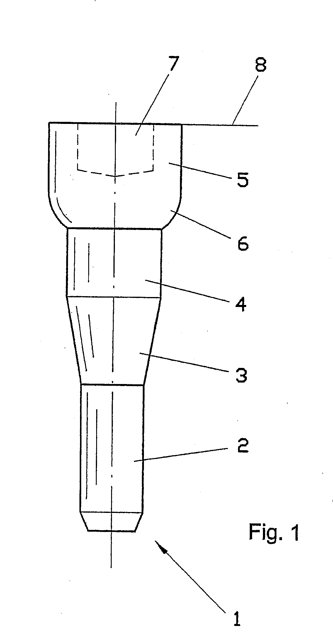
[0026]Referring to the drawings in particular, the ball pivot blank shown in FIG. 1 is manufactured by means of an extrusion process and comprises essentially a plurality of partial areas of different three-dimensional shapes arranged one after another in the longitudinal direction of the ball pivot. After extrusion, the different areas are to be formed into their final shape by means of the combination of process features that are essential for the present invention, and a ball pivot shape corresponding to the view in FIG. 3C is obtained after completion of the cold forming according to the present invention.

[0027]Thus, the ball pivot blank, designated by 1 as a whole, comprises, according to the view in FIG. 1, a cylindrical area 2, which is arranged at a free end of the ball pivot blank 1 and on which a thread for fastening the ball pivot to a machine or body component is located after the completion of the ball pivot. The cylindrical area 2 is joined directly by a cone area 3. T...


PUM

PropertyMeasurementUnit
Areaaaaaaaaaaa
Fatigue strengthaaaaaaaaaa

Abstract

A cold forming process for manufacturing ball pivots with a ball area, a cone area and a thread area for installation in ball and socket joints by cold forming is presented, in which a ball pivot blank (1) with a shaped cone area (3) and cylindrical areas for the thread (2) and the ball (5) is manufactured at first from a bar-shaped semifinished bar stock by extrusion. The extrusion operation is followed by the forming of the ball area as another manufacturing step by means of a rolling processes. At the same time, the thread area can be formed in its final shape. Thus, the ball pivot is manufactured as a whole by cold forming only and it makes it possible to significantly increase the production output per unit of time compared to the processes known from the state of the art. At the same time, it is possible to use less expensive grades of steel, because sufficient fatigue strength of the ball pivot can be guaranteed by the cold forming.

Description

CROSS REFERENCE TO RELATED APPLICATIONS[0001]This application is a United States National Phase application of International Application PCT / DE 2004 / 002614 and claims the benefit of priority under 35 U.S.C. § 119 of German Patent Application DE 103 56 111.0 filed Nov. 27, 2003, the entire contents of which are incorporated herein by reference.FIELD OF THE INVENTION[0002]The present invention pertains to a cold forming process for manufacturing ball pivots with a ball area, a cone area and a thread area for installation in ball and socket joints.BACKGROUND OF THE INVENTION[0003]Machining as well as non-machining manufacturing processes are used, in principle, to manufacture ball pivots that are intended for installation in ball and socket joints. Larger amounts of waste material, which must be disposed of, take place during machining. In addition, there is a disadvantage that the waste material must first be purchased as a semifinished product. In addition, it is disadvantageous that...

Claims


Application Information

Patent Timeline
IPC IPC(8): B21D53/10B21H1/00B21H1/18B21H7/18B21K1/02B21K1/76B23P15/00F16C11/06
CPCB21H1/00B21H1/18B21H7/182B21K1/02Y10T29/49664B23P15/00B23P2700/11F16C11/0604B21K1/762F16C2220/48B21H7/00
Inventor KRUSE, JOCHENROSENBERGER, KLAUS
Owner ZF FRIEDRICHSHAFEN AG
Learn More