
Molten glass delivery apparatus for optical quality glass

a delivery apparatus and glass technology, applied in the field of manufacturing optical quality glass, can solve the problems of large number of defects that cannot be removed, finer is diverted to the unusable, etc., and achieve the effects of increasing the bandwidth of glass flow rate control, high aspect ratio, and increasing fining efficiency

Active Publication Date: 2009-02-12
CORNING INC
View PDF24 Cites 20 Cited by
  • Summary
  • Abstract
  • Description
  • Claims
  • Application Information

AI Technical Summary

Benefits of technology

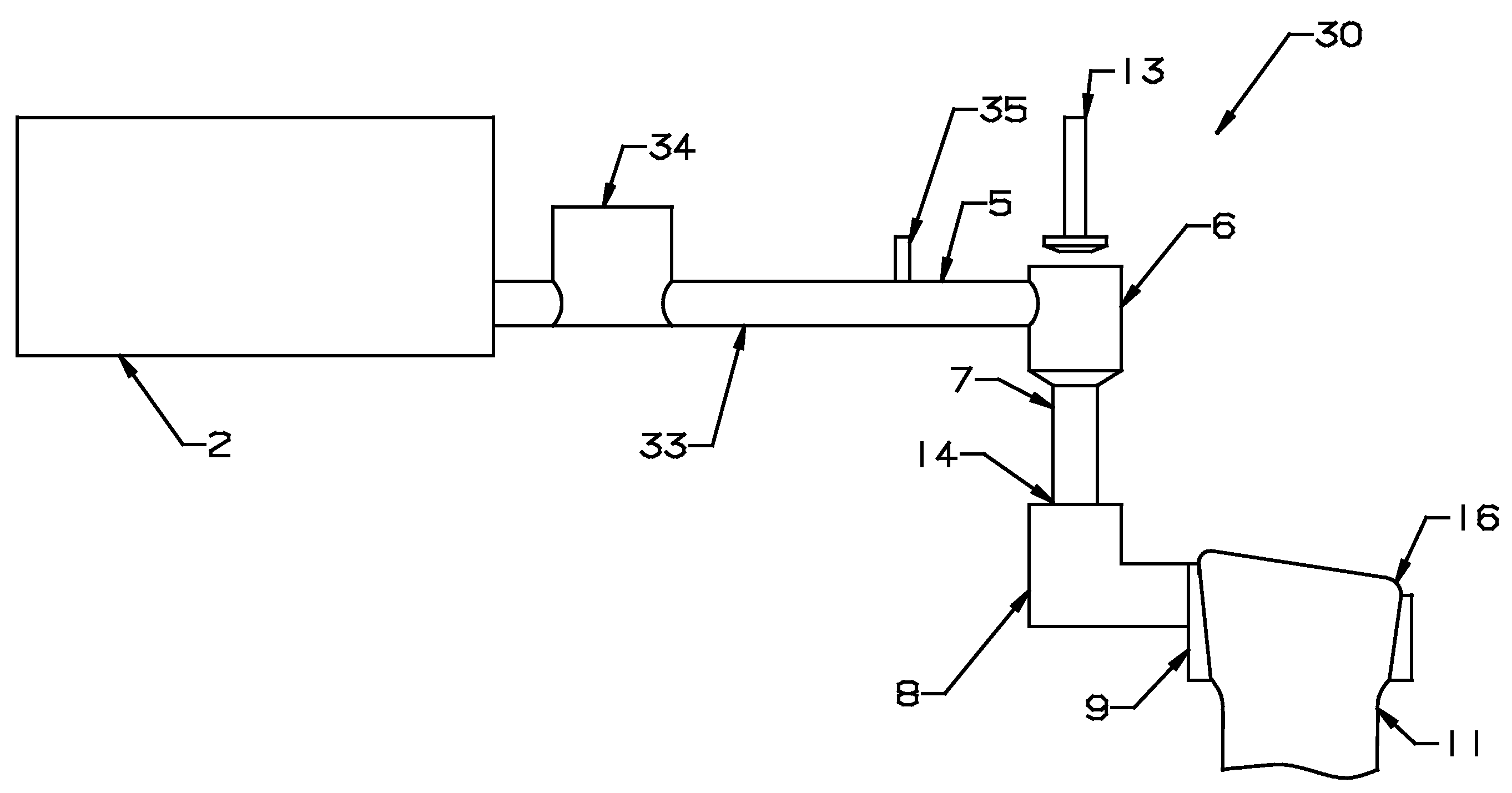
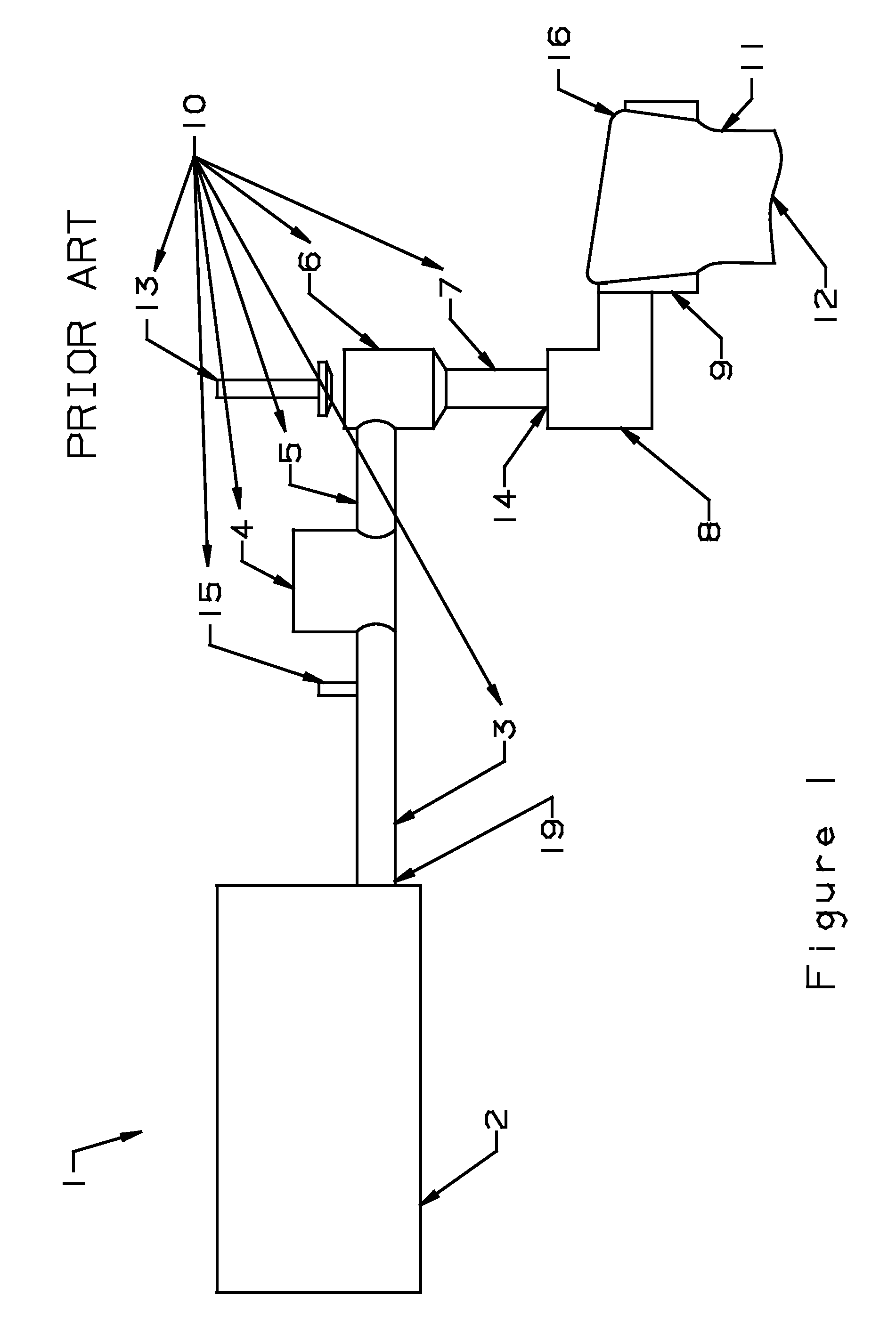
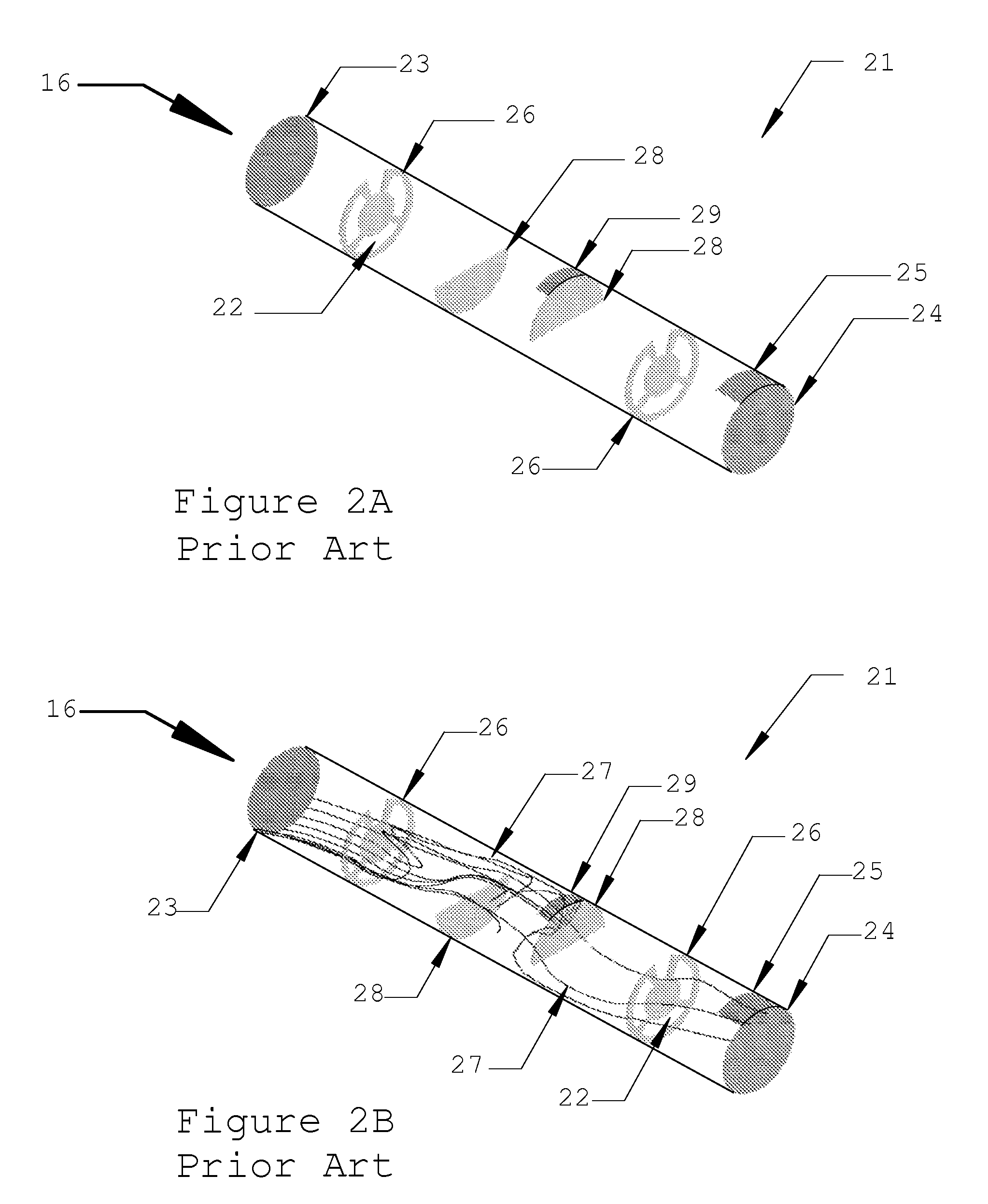
[0028]The present invention significantly modifies the prior art glass delivery system from the furnace to the glass forming process to match it with the overflow downdraw process. A substantial number of defects not removed by the finer are diverted to the unusable inlet and distal edges of the sheet. In one embodiment, the stirring device is relocated to the inlet of the finer from the outlet of the finer. In another embodiment, the basic shape of the finer is preferably changed from a cylindrical shape to a Double Apex (or Gull Wing) shaped cross-section whereby the apexes of the finer contain the glass that will form the unusable inlet end of the glass sheet. The finer vent or vents are preferably located at these apexes such that any homogeneity defects caused by the vents are diverted to the unusable inlet end of the glass sheet. The finer cross-section has a high aspect ratio for increased fining efficiency as compared to a cylindrical finer.
[0030]In another embodiment the stirrer speed is used to increase the bandwidth of glass flow rate control.
[0032]The present invention improves the fining capability of the delivery system apparatus by matching the flow characteristic of the delivery system to the overflow downdraw process.

Problems solved by technology

A substantial number of defects not removed by the finer are diverted to the unusable inlet and distal edges of the sheet.

Method used


Image

  • Molten glass delivery apparatus for optical quality glass
  • Molten glass delivery apparatus for optical quality glass
  • Molten glass delivery apparatus for optical quality glass

Examples


Embodiment Construction

[0123]The present invention relates to the apparatus termed the delivery system, which transfers and conditions the glass from the furnace to the forming process. The flow characteristics of the glass in the overflow downdraw process are unique and of a character that has led to the invention of a new configuration of the delivery system. The present invention reorganizes and redesigns the component parts of the delivery system and allows for the use of equipment thought detrimental to the quality requirements of the overflow downdraw process.

[0124]The present invention is related to the physical aspect of fining, which is affected by the shape of the finer apparatus. Specifically, in one embodiment, the shape of the fining apparatus in the present invention is matched to the flow characteristics of the overflow downdraw sheet glass manufacturing process. For a given glass, the variation of the glass density in the fining process is a second order effect, thus the present invention ...


PUM

PropertyMeasurementUnit
Angleaaaaaaaaaa
Temperatureaaaaaaaaaa
Lengthaaaaaaaaaa

Abstract

A molten glass delivery system is modified to match it with the overflow downdraw process. A substantial number of defects not removed by the finer are diverted to the unusable inlet and distal edges of the sheet. In one embodiment, the stirring device is relocated from the outlet to the inlet of the finer. In another embodiment, the basic shape of the finer is preferably changed from a cylindrical shape to a Double Apex (or Gull Wing) shaped cross-section, whereby the apexes of the finer contain the glass that will form the unusable inlet end of the glass sheet. The finer vent or vents are preferably located at these apexes such that any homogeneity defects caused by the vents are diverted to the unusable inlet end of the glass sheet. The finer cross-section has a high aspect ratio for increased fining efficiency as compared to a cylindrical finer.

Description

REFERENCE TO RELATED APPLICATIONS[0001]This application claims one or more inventions which were disclosed in Provisional Application No. 60 / 954,622, filed Aug. 8, 2007, entitled “MOLTEN GLASS DELIVERY APPARATUS FOR THE OVERFLOW DOWNDRAW SHEET FORMING PROCESS” and Provisional Application No. 60 / 957,007, filed Aug. 21, 2007, entitled “MOLTEN GLASS DELIVERY APPARATUS FOR THE OVERFLOW DOWNDRAW SHEET FORMING PROCESS”. The benefit under 35 USC §119(e) of the United States provisional applications is hereby claimed, and the aforementioned applications are hereby incorporated herein by reference.BACKGROUND OF THE INVENTION[0002]1. Field of the Invention[0003]This invention relates generally to the manufacture of optical quality glass. More specifically, it is especially useful for the manufacture of glass sheet made by the overflow downdraw process for the production of TFT / LCD display devices that are widely used for television and computer displays.[0004]2. Description of Related Art[000...

Claims


Application Information

Patent Timeline
IPC IPC(8): C03B5/18C03B5/00C03B5/26
CPCC03B5/187C03B5/1875C03B5/225C03B17/064C03B5/262C03B7/02C03B5/2252
Inventor PITBLADDO, RICHARD B.
Owner CORNING INC
Learn More