Spectroscopy device, spectroscopy apparatus and spectroscopy method
- Summary
- Abstract
- Description
- Claims
- Application Information
AI Technical Summary
Benefits of technology
Problems solved by technology
Method used
Image

Examples
first embodiment
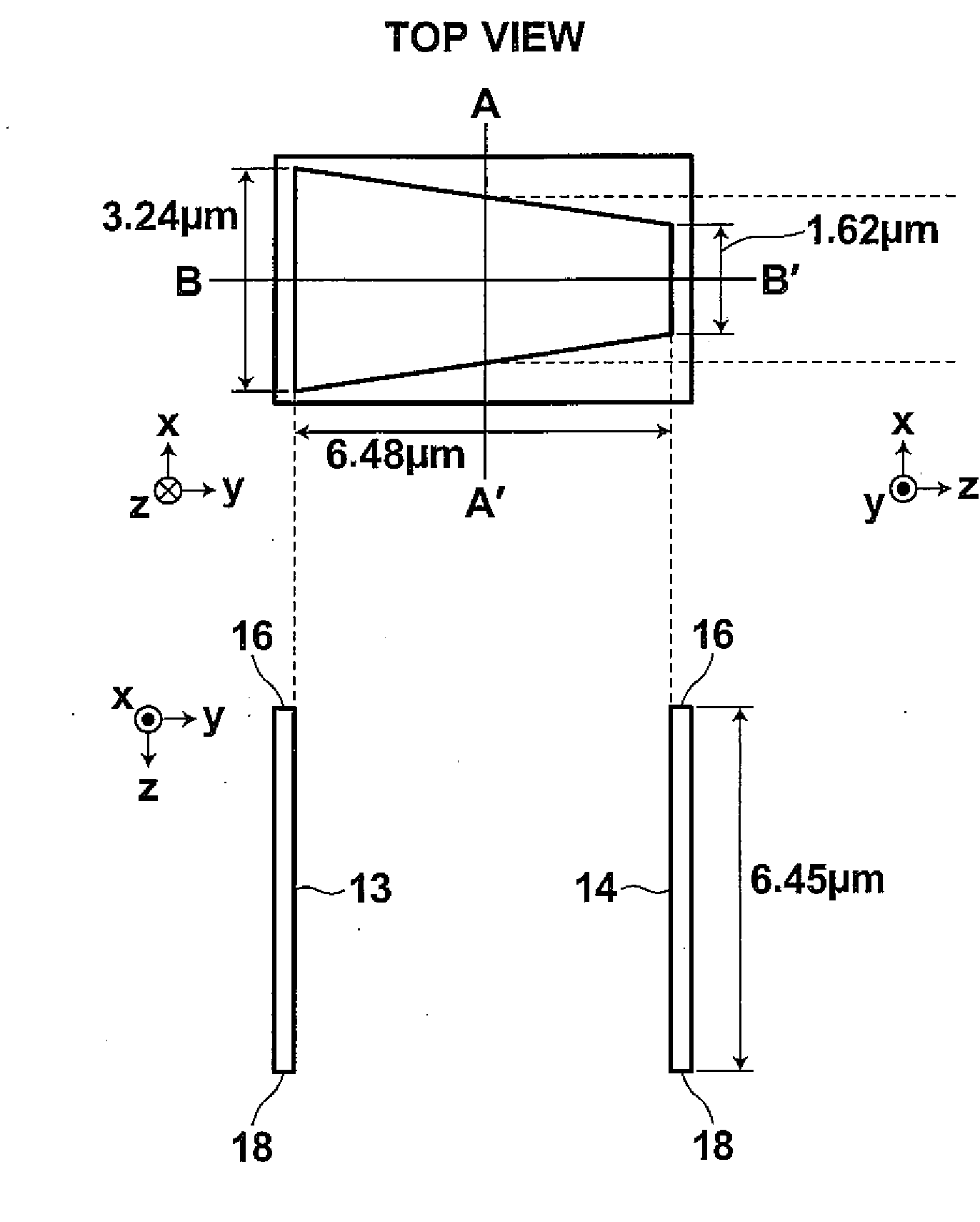
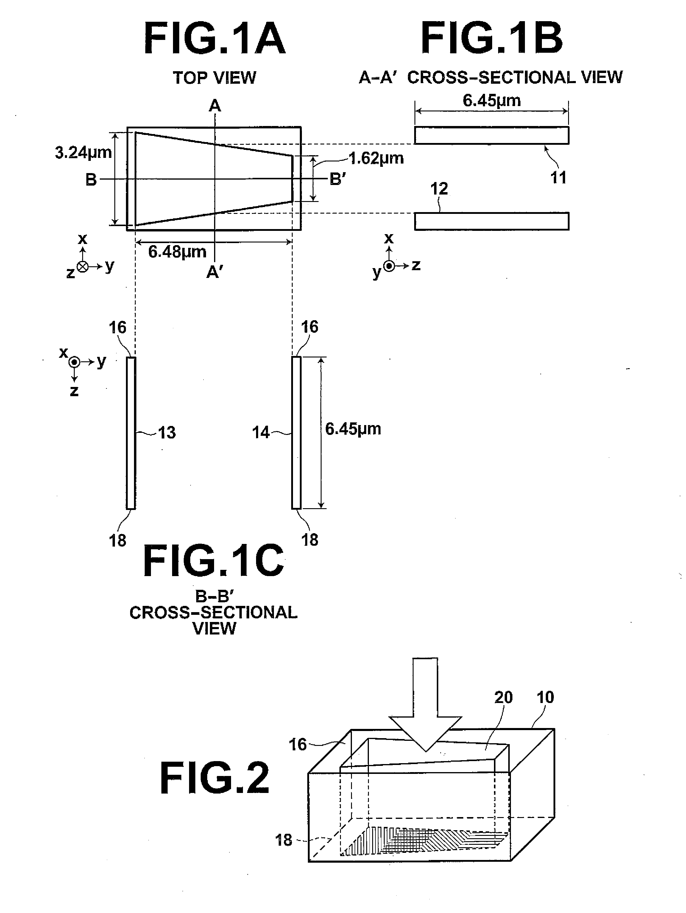
[0051]FIGS. 1A, 1B, 1C illustrate an example structure of the spectroscopy device 10 of the present invention. FIG. 1A is a top view of the spectroscopy device 10, illustrating the shape thereof viewed from the light input face. The spectroscopy device 10 is a structure made of a metal plate having a uniform thickness with an aperture 20 vertically running from the upper face, that is, input face to the bottom face, that is, output face. FIG. 1A depicts as if one spectroscopy device were independent from other spectroscopy devices, but it is preferable to have a structure in which the metal plate is shared by other adjacent spectroscopy devices from the standpoint of manufacture and use. Accordingly, the outer shape shown in FIG. 1A is an imaginary shape. FIG. 1B is a cross-sectional view taken along the line A-A′ in FIG. 1A. The metal plate forming the structure of the spectroscopy device 10 reflects input light on the inner walls of the aperture 20. In the present embodiment, the ...
first modification
of First Embodiment
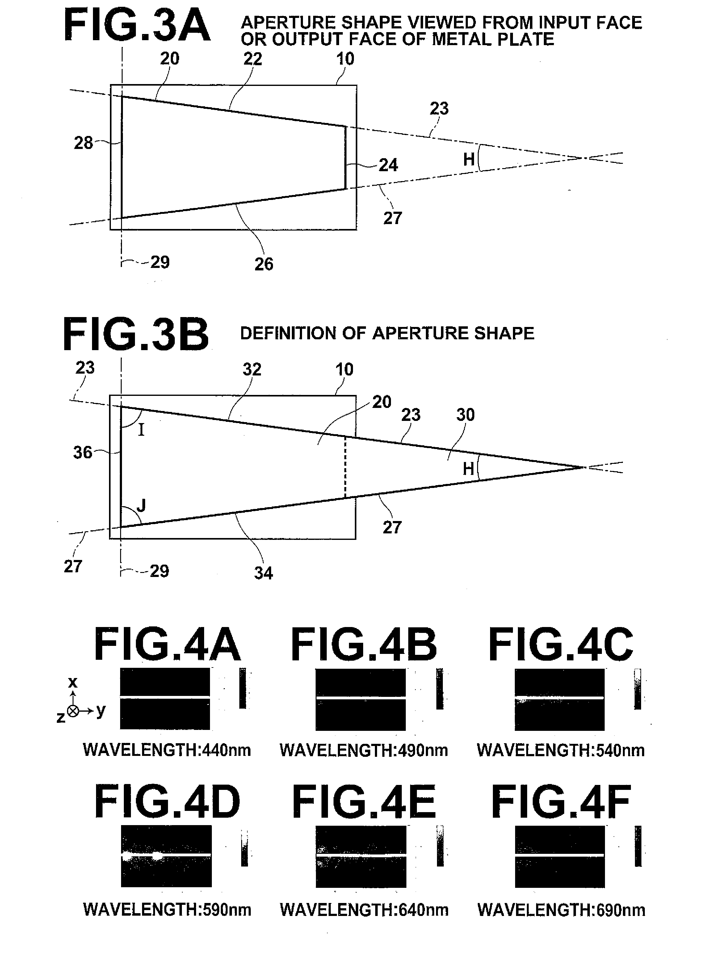
[0062]FIGS. 7A to 7F illustrate spectroscopic results of X direction polarized input light using the spectroscopy device of the present invention. The coordinate system shown on the left of FIG. 7A corresponds to the coordinate system of the spectroscopy device shown in FIG. 1A. FIGS. 7A to 7F illustrate the manners in which input light is spectrally separated at each of six wavelengths from 440 nm (FIG. 7A) to 690 nm (FIG. 7F). In each of the graphs in FIG. 7A to 7F, a more whitish portion represents a peak where the light having the wavelength is present strongly as standing wave. The peak position varies with the wavelength, showing that the spectroscopy device of the present embodiment functions as a spectroscopy device. Unlike the results of Y direction polarized light shown in FIGS. 4A to 4F, line like peaks parallel to X axis are observed.
[0063]FIG. 8 illustrates spectral intensity of X direction polarized input light using the spectroscopy device shown in ...
second modification
of First Embodiment
[0064]FIGS. 9A, 9B illustrate modified examples of the shape of the aperture of the spectroscopy device of the present invention. FIGS. 9A, 9B are basically identical, so that FIG. 9B will primarily be described here. The aperture 92 of spectroscopy device of the present embodiment is defined in the following manner. Namely, the geometry enclosed by extended lines of three sides, side 22, side 26, and side 28 of those forming the aperture 92, that is, the geometry enclosed by the extended line 23, extended line 27, and extended line 29 forms an isosceles triangle 30 with a narrow apex angle H, that is, forms a triangle. The shape of the aperture 92 shown in FIG. 9B is a trapezoid which is formed by cutting an apex section of the isosceles triangle 30 parallel to the bottom side 28 thereof. The aperture 92 differs from that of the first embodiment in that it has rounded corners.
[0065]In FIG. 9A, the corners are rounded with Ra=0.1 μm, and in FIG. 9B, the corners ar...
PUM
 Abstract
Description
Claims
Application Information