Connection structure of photoelectric flexible wiring board, connector and photoelectric flexible wiring board

a technology of photoelectric flexible wiring and connectors, which is applied in the direction of coupling device connections, instruments, optical elements, etc., can solve the problems of unnecessarily large size of the photoelectric difficult to apply the flexible wiring board b>2/b> to such a use requiring high flexibility, and achieves convenient application to small devices, improved flexibility, and reduced size

Active Publication Date: 2009-02-12
HOSIDEN CORP
View PDF3 Cites 12 Cited by
  • Summary
  • Abstract
  • Description
  • Claims
  • Application Information

AI Technical Summary

Benefits of technology

[0029]In the connection structure of the photoelectric flexible wiring board according to the present invention, the length of the optical transmission line can be extended to a length substantially equal to the entire length of the wiring board since the photoelectric flexible wiring board is provided excluding the photonic device and the driver therefor that are associated with the photoelectric flexible wiring board and the photonic device is mounted in the connector. The photoelectric flexible wiring board can therefore be reduced in size in securing a necessary length for the optical transmission line, and the wiring board can easily be applied to small devices. Moreover, the photoelectric flexible wiring board is improved in flexibility because of the omission of less flexible mounting portions, resulting in reduced manufacturing costs. Further, since photoelectric conversion is not performed on the photoelectric flexible wiring board, the wiring board can maintain the optical transmission characteristics, providing an effective measure for electromagnetic compatibility (EMC) and against degradation of signals.
[0030]Because the connector for the photoelectric flexible wiring board according to the present invention is mounted with the photonic device at a position corresponding to the optical transmission line in the photoelectric flexible wiring board, the photonic device and the driver therefor can be removed from the photoelectric flexible wiring board. With this structure, the length of the optical transmission line in the photoelectric flexible wiring board can be extended to a length substantially equal to the entire length of the wiring board, so that the photoelectric flexible wiring board can be reduced in size in securing a necessary length for the optical transmission line and can be easily applied to small devices. Also, the exclusion of the less flexible mounting portions from the photoelectric flexible wiring board increases the flexibility of the photoelectric flexible wiring board, and the manufacturing costs thereof can thus be reduced. Moreover, because photoelectric conversion need not be performed on the photoelectric flexible wiring board, the wiring board can maintain the optical transmission characteristics, providing an effective measure for EMC and against degradation of signals.
[0031]Furthermore, in the photoelectric flexible wiring board according to the present invention, the end portions thereof does not have mounting portions for the photonic devices and the drivers therefor, both the optical and electrical transmission lines extend up to the ends of the board, and the signal entrance-cum-exits for the both kinds of signals are provided at the ends of the respective transmission lines. Therefore, the wiring board is highly flexible, and the width of the board can be reduced. Because the wiring board does not handle conversion from optical signals to electrical signals, avoiding a situation where high-speed digital signals pass through the electrical transmission lines, the photoelectric flexible wiring board can maintain EMC characteristics and transmission characteristics for high-speed digital signals.

Problems solved by technology

Therefore, the photoelectric flexible wiring board 2 has an unnecessarily large size, because of which its application to small apparatuses is difficult.
This is the first problem.
For this reason, it is difficult to apply the flexible wiring board 2 to such a use requiring high flexibility as clamshell cellular phones.
This is the second problem.
The third problem is increased costs for the photoelectric flexible wiring board 2 due to a process of mounting the photonic devices 3 and drivers 4 therefor in fabrication of the board 2.
The fourth problem is that the substantial length of the optical transmission line is limited in comparison with the entire length L1 of the photoelectric flexible wiring board 2.
Therefore, advantages of optical transmission are not fully utilized.
Specifically, these electrical transmission lines disadvantageously cause deterioration in electromagnetic compatibility (EMC) characteristics, degradation in signal transmission characteristics, and the like.

Method used


Image

  • Connection structure of photoelectric flexible wiring board, connector and photoelectric flexible wiring board
  • Connection structure of photoelectric flexible wiring board, connector and photoelectric flexible wiring board
  • Connection structure of photoelectric flexible wiring board, connector and photoelectric flexible wiring board

Examples


Embodiment Construction

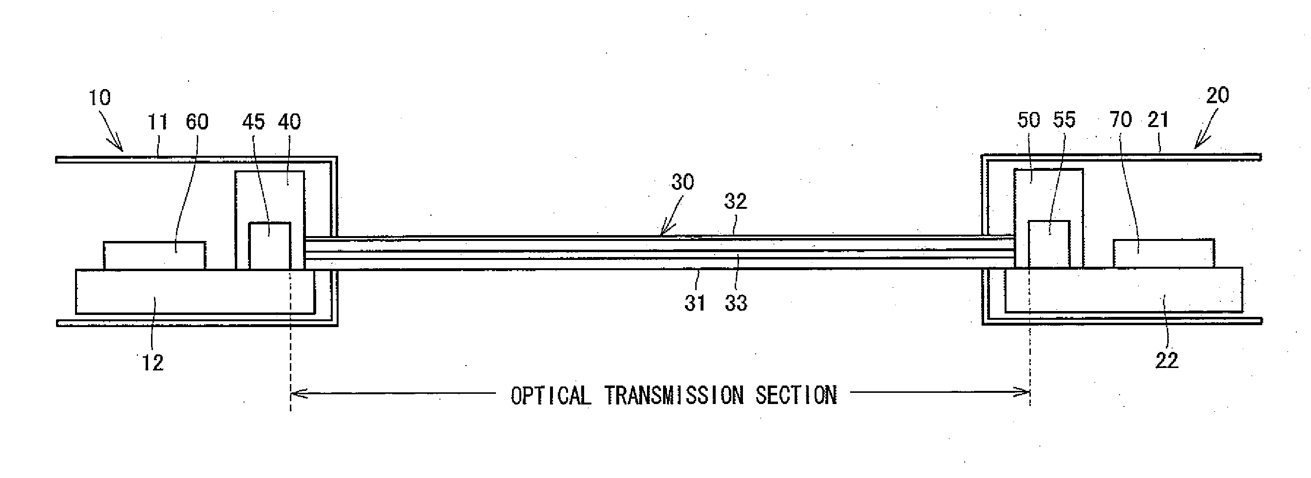
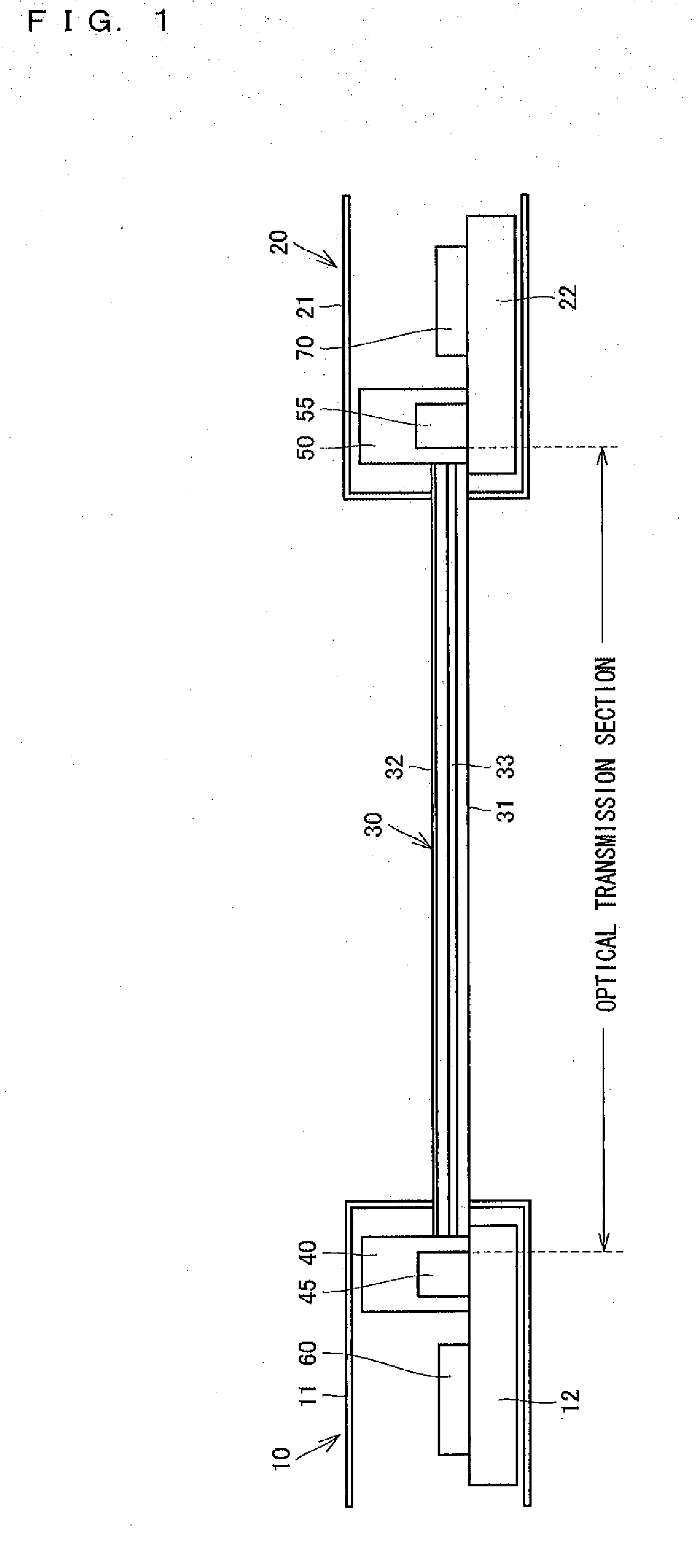
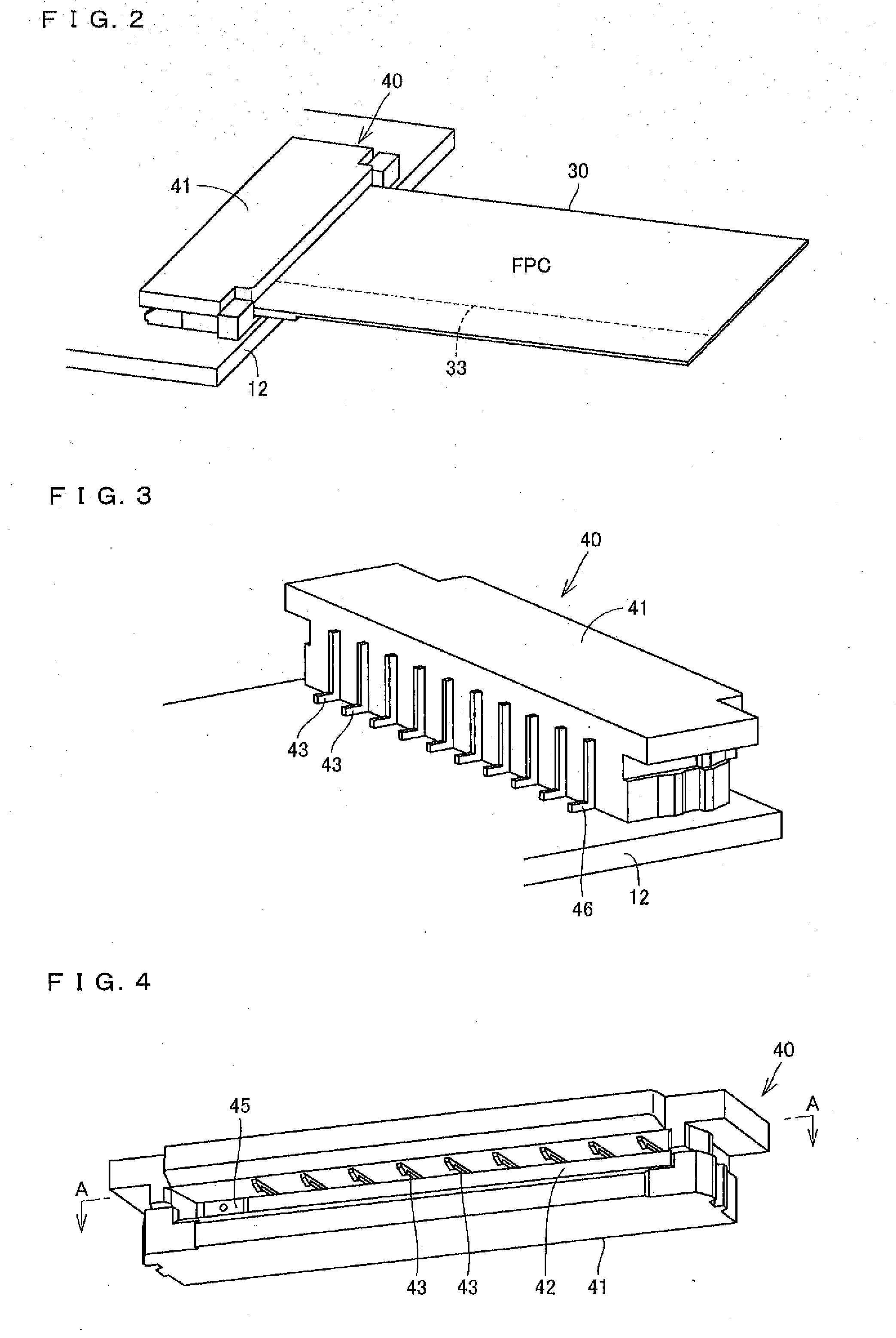
[0032]Embodiments of the present invention will be described in detail below with reference to the drawings. FIG. 1 is a schematic configuration view illustrating a wiring structure of an photoelectric flexible wiring board according to an embodiment of the present invention, FIG. 2 is a perspective view of the photoelectric flexible wiring board and a connector in use in the wiring structure, FIG. 3 is a perspective view of the connector in use as viewed from the rear side thereof, FIG. 4 is a perspective view of the connector as viewed from the front side thereof, and FIG. 5 is a transverse cross-sectional plan view of the connector, viewed along arrows A-A in FIG. 4.

[0033]As shown in FIG. 1, a wiring structure of an photoelectric flexible wiring board according to the present embodiment is used in information processing terminal apparatus with a rotating portion to connect an electric circuit in a main body 10 with an electric circuit in a cover body 20. With the main body 10 bei...


PUM


Abstract

[Problems to be Solved] The present invention provides a longer optical transmission line in an photoelectric flexible wiring board to downsize the photoelectric flexible wiring board and obtaining high flexibility and good optical transmission characteristics.
[Means for Solving the Problems] In an photoelectric flexible wiring board 30, photonic devices 45 and 55 performing photoelectric conversion and drivers 60 and 70 therefor are excluded. The photonic devices 45 and 55 are mounted in connectors 40 and 50 for connecting the photoelectric flexible wiring board 30 to mounting boards 12 and 22. The drivers 60 and 70 are mounted on the mounting boards 12 and 22 together with the connectors 40 and 50.

Description

TECHNICAL FIELD[0001]The present invention relates to a connection structure of an photoelectric flexible wiring board transmitting both optical and electrical signals, for connecting the wiring board to another board such as a rigid board. The invention also relates to a connector and an photoelectric flexible wiring board for use in the connection structure of the photoelectric flexible wiring board.BACKGROUND ART[0002]High-speed performance has been demanded of information processing terminal apparatuses supporting the recent high-speed communication networks. As one approach for meeting the demand, optical-electrical mixed circuit boards have been developed, which transmit both optical and electrical signals with a single board. The feature of the optical-electrical mixed circuit board resides in the parallel arrangement of an optical transmission line relative to a plurality of electrical transmission lines. As one type of such an optical-electrical mixed circuit board, a photo...

Claims


Application Information

Patent Timeline
Patent Type & Authority Applications(United States)
IPC IPC(8): G02B6/12
CPCG02B6/3817G02B6/3897G02B6/43G02B6/4292G02B6/4214G02B6/10H01R12/78
Inventor KONDO, HAYATONAGATA, TAKAYUKI
Owner HOSIDEN CORP
Why Eureka
Try Eureka