

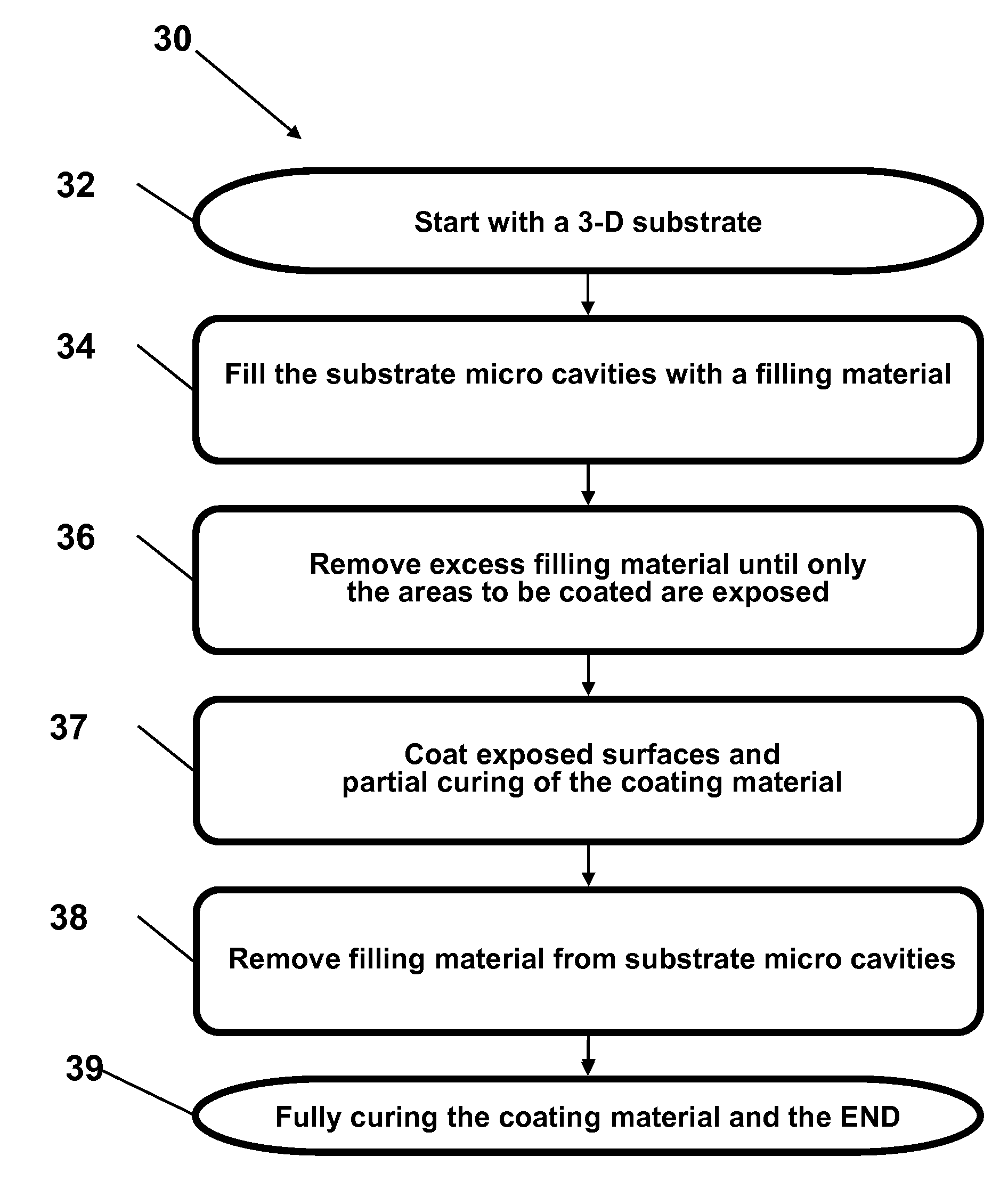
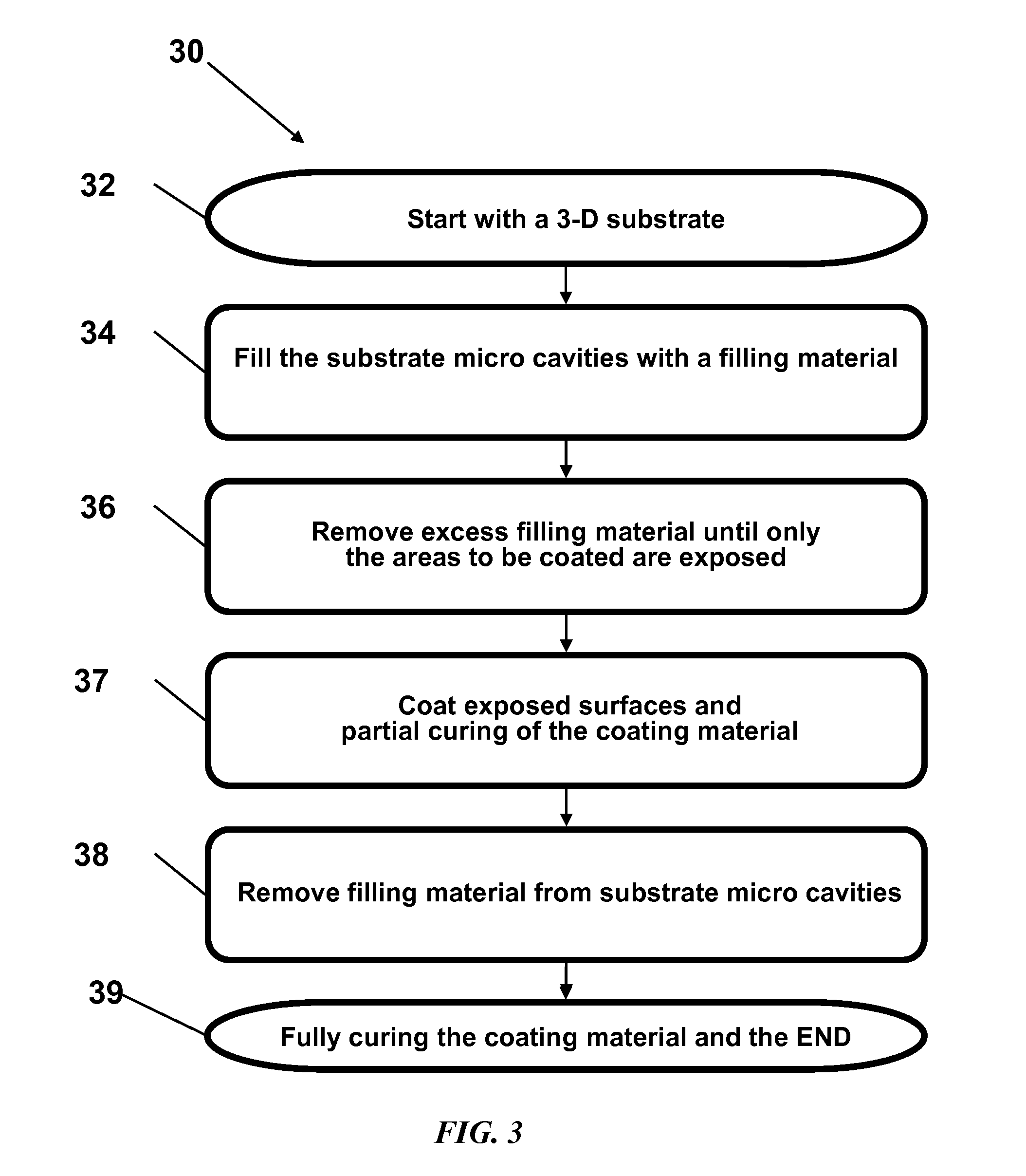
Methods for liquid transfer coating of three-dimensional substrates
a three-dimensional substrate and liquid transfer coating technology, applied in the direction of sustainable manufacturing/processing, semiconductor/solid-state device testing/measurement, separation processes, etc., can solve the problem that conventional coating methods cannot provide the liquid coating on the selective surface (top surface or ridge) of 3-d microstructures that is required in many applications, and achieve the effect of reducing surface tension
- Summary
- Abstract
- Description
- Claims
- Application Information
AI Technical Summary
Benefits of technology
Problems solved by technology
Method used
Image

Examples
Embodiment Construction
[0033]The following description is not to be taken in a limiting sense, but is made for the purpose of describing the general principles of the present disclosure. The scope of the present disclosure should be determined with reference to the claims. And although described with reference to the manufacture and coating of 3-D TFSS, a person skilled in the art could apply the principles discussed herein to the manufacture and coating of any multi-dimensional substrate.
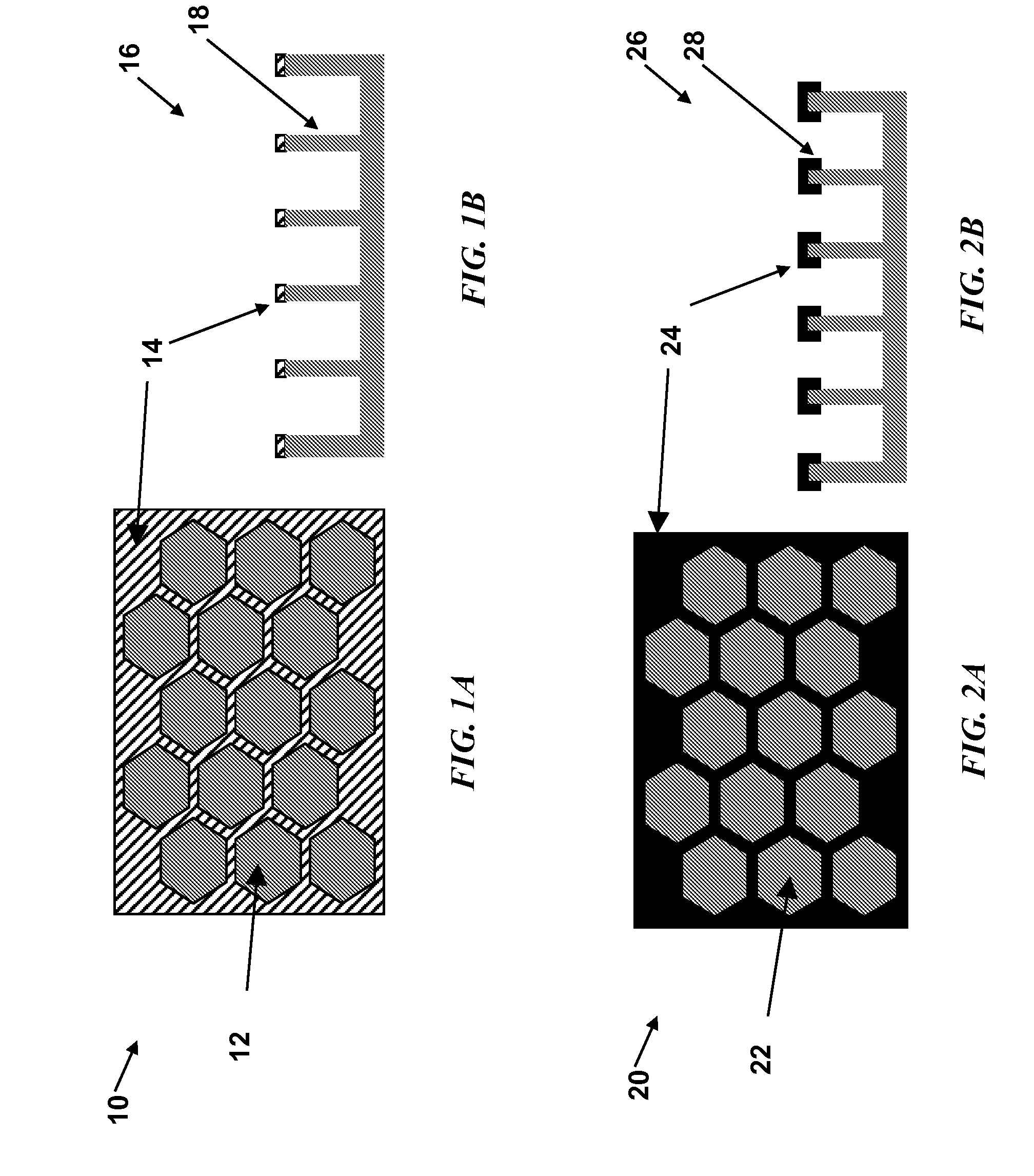
[0034]Preferred embodiments of the present disclosure are illustrated in the drawings, like numbers being used to refer to like and corresponding parts of the various drawings. The innovative 3-D TFSS substrate designs and technologies of the current disclosure are based on the use of a three-dimensional (3-D), self-supporting, semiconductor thin film, deposited on and released from a reusable crystalline (embodiments include monocrystalline or multicrystalline silicon) semiconductor template, and methods for selectively...
PUM
 Abstract
Description
Claims
Application Information