

Method and Device for Redundantly Supplying Several Electric Servomotors or Drive Motors by Means of a Common Power Electronics Unit
- Summary
- Abstract
- Description
- Claims
- Application Information
AI Technical Summary
Benefits of technology
Problems solved by technology
Method used
Image

Examples
Embodiment Construction
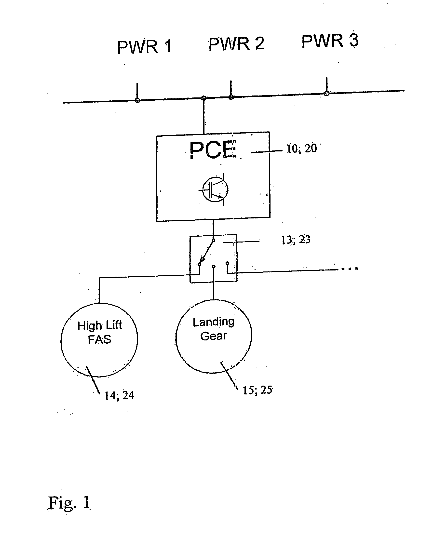
[0047]FIG. 1 shows a highly simplified diagram of a sequential utilization, i.e., a successive or alternate utilization, of common power electronics 10; 20 (PCE, Power Control Electronics) by different aircraft systems, namely a high lift system (High Lift FAS) and a landing gear (Landing Gear) that respectively contain servomotors or drive motors 14, 24 and 15; 25 that are supplied by the common power electronics 10; 20 and selectively connected, i.e., in accordance with the respective requirements, to the power electronics 10; 20 by a switching device 13; 23 in order to be supplied with energy. The power supply of the power electronics 10; 20 is realized with various redundant power supplies PWR (Power) 1 to 3 as schematically indicated in FIG. 1.
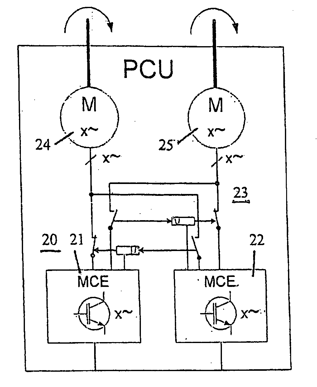
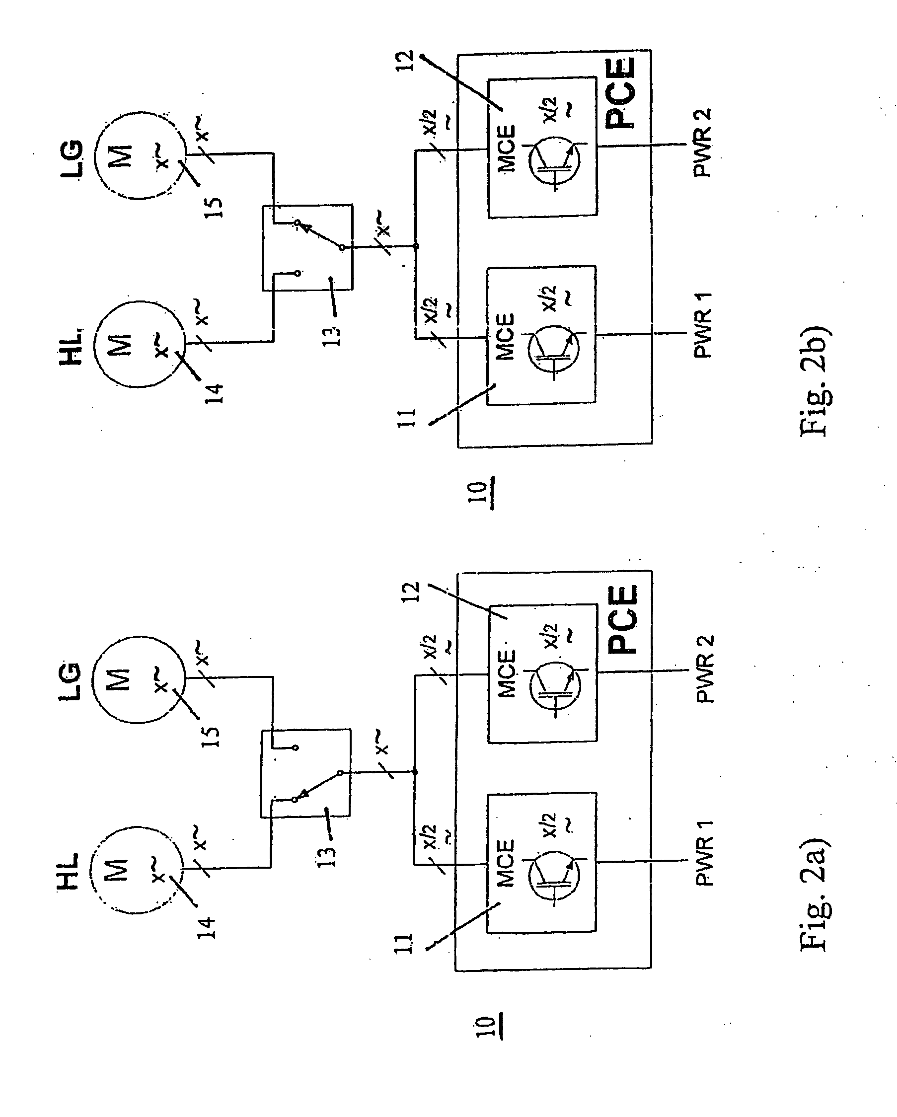
[0048]FIGS. 2a) and b) respectively show a circuit diagram of a system according to one embodiment of the invention, in which common power electronics 10 abbreviated in the form of PCE (Power Control Electronics) are utilized sequentially...
PUM
 Abstract
Description
Claims
Application Information