Structured illumination for imaging of stationary and non-stationary, fluorescent and non-fluorescent, objects

Inactive Publication Date: 2009-02-19
UNIVERSITY OF ROCHESTER
View PDF5 Cites 53 Cited by
  • Summary
  • Abstract
  • Description
  • Claims
  • Application Information

AI Technical Summary

Benefits of technology

[0016]It is therefore an object of the invention to make the imaging of stationary fluorescent objects more robust by improving phase calibration.

Problems solved by technology

Techniques for superresolution and optical sectioning reveal an abundance of information which is not accessible to scientists with conventional methods of imaging.
However, the retina in vivo is not significantly fluorescent by nature and is never completely stationary.
Therefore the advantages of structured illumination imaging have not yet been extended to retinal imaging.
However it is not possible to use them to detect diseases in their early stage, to detect microscopic retinal damage, or to study the cellular structure of a healthy retina.
When the pupil aperture is small and undilated, such as 3 mm in diameter, mild aberrations are not significant enough to demand correction.
But when the pupil is dilated to 6-8 mm in diameter for retinal imaging, even small aberrations add significant blur to the image.
But there are several structures that are smaller than 2 microns in size such as rods, foveal cones, fine blood capillaries, ganglion cell axons and dendrites, etc., which have been observed in vitro, but are not easily resolved in vivo for the human retina in most instruments.
It is not possible to dilate a patient's pupil greater than 6-8 mm diameter.
Hence the frequencies that are captured by the optical imaging system are limited by the size of this aperture of the eye.
The axial resolution of an imaging system is also limited similarly by diffraction.
In most in vivo imaging of the retina, the light scattered from the cornea and lens and the out of focus light from different planes in the retina often results in low contrast of the images.
This signal is weak enough to be lost in most wide field imaging systems.
But they involve elaborate and expensive equipment.
Structured-illumination-based axial sectioning setups are several times less expensive.
Often tissues, cells and semiconductor chips may be damaged and change in structural and functional composition due to the addition of fluorophores.
This is often inadvisable for scientific research.
Yet another issue is that sinusoidal illumination imaging for superresolution and axial sectioning has only been implemented on stationary specimens such as fixed slides on a vibration-free microscope.
Usually these phase shifts are imparted in definite known steps using expensive, calibrated, precision actuation equipment.
Hence it is not possible to impart known phase shifts of definite step sizes to such a randomly moving object specimen.

Method used


Image

  • Structured illumination for imaging of stationary and non-stationary, fluorescent and non-fluorescent, objects
  • Structured illumination for imaging of stationary and non-stationary, fluorescent and non-fluorescent, objects
  • Structured illumination for imaging of stationary and non-stationary, fluorescent and non-fluorescent, objects

Examples


Embodiment Construction

[0053]Preferred embodiments of the present invention will now be set forth in detail with reference to the drawings, in which like reference numerals refer to like elements or steps throughout.

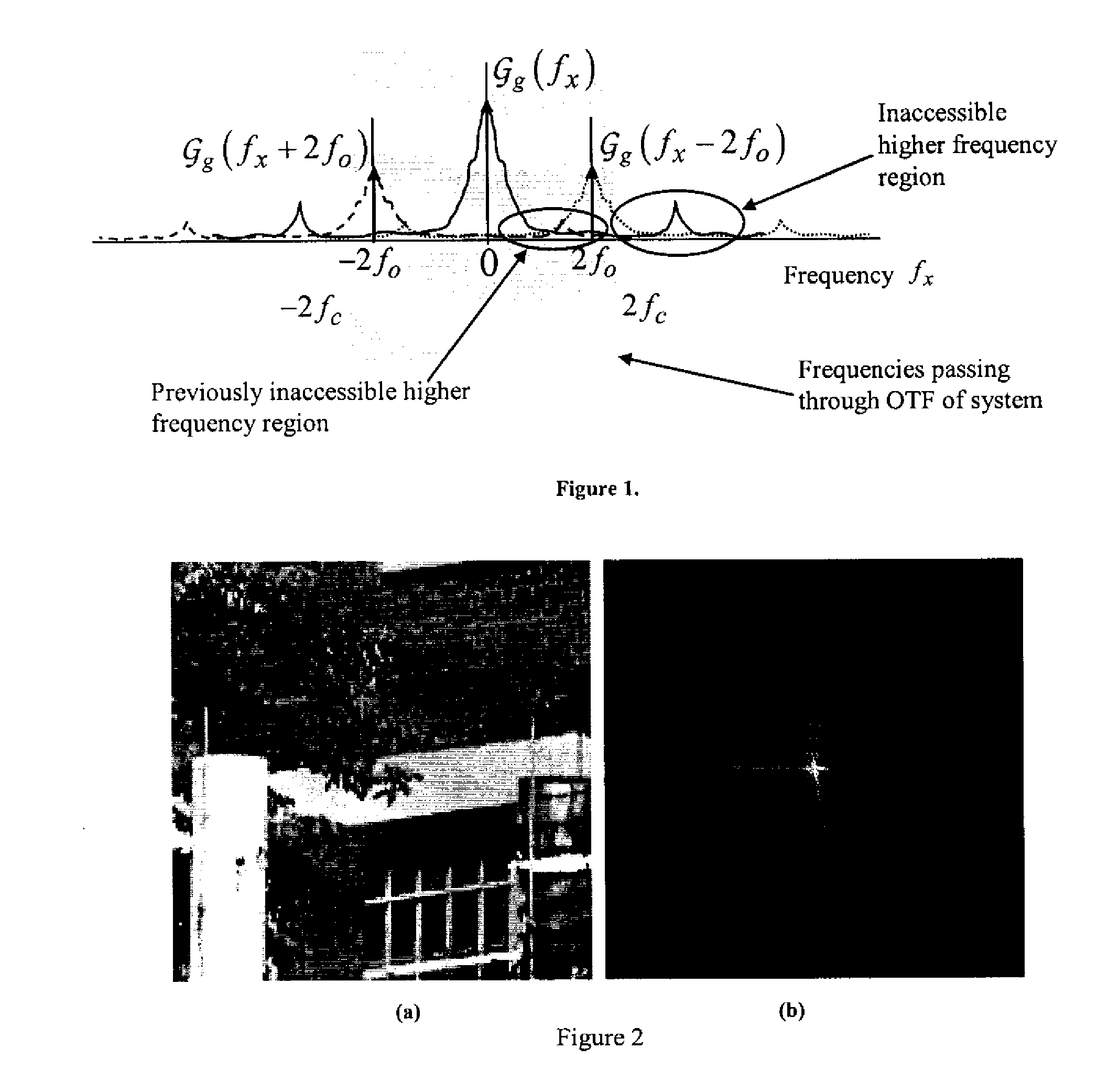
[0054]First, superresolution with sinusoidal illumination in the incoherent case will be considered. Here we assume interaction for light absorption and emission linear in intensity. We demonstrate the case of incoherent illumination such as a metal halide lamp and incoherent fluorescent emission. The sinusoidal pattern is produced by a grating in the illumination path.

[0055]The phase estimation analysis which follows is also applicable to the case where a coherent laser illumination is used to project sinusoidal fringes on a fluorescent object. Our method should also be valid for coherent illumination and coherent imaging which is the case of non-fluorescent objects under coherent laser fringe illumination.

[0056]Images are formed in the following manner. Assume a vertical sinusoidal illuminat...


PUM


Abstract

An object to be imaged is illuminated with a structured (e.g., sinusoidal) illumination at a plurality of phase shifts to allow lateral superresolution and axial sectioning in images. When an object is to be imaged in vitro or in another situation in which the phase shifts cannot be accurately determined a priori, the images are taken, and the phase shifts are estimated a posteriori from peaks in the Fourier transforms. The technique is extended to the imaging of fluorescent and non-fluorescent objects as well as stationary and non-stationary objects.

Description

REFERENCE TO RELATED APPLICATION[0001]The present application claims the benefit of U.S. Provisional Patent Application Ser. No. 60 / 907,579, filed Apr. 10, 2007, whose disclosure is hereby incorporated by reference in its entirety into the present disclosure.STATEMENT OF GOVERNMENT INTEREST[0002]The work leading to the present invention was supported by NIH Grant No. EY 001319. The government has certain rights in the invention.FIELD OF THE INVENTION[0003]The present invention is directed to structured illumination imaging and its application to stationary and non-stationary, fluorescent and non-fluorescent objects. A particular case is in vivo imaging, particularly retinal imaging.DESCRIPTION OF RELATED ART[0004]Structured illumination imaging is a technique used for lateral superresolution and axial optical sectioning (3D imaging). Images of objects such as cells, tissue, fibers, etc are often blurred by the limited size of the numerical aperture of the microscope and the out of f...

Claims


Application Information

Patent Timeline
IPC IPC(8): H04N5/228
CPCA61B3/12A61B5/0059A61B3/10G01N21/45G01N21/6458A61B5/7257
Inventor SHROFF, SAPNAWILLIAMS, DAVIDFIENUP, JAMES
Owner UNIVERSITY OF ROCHESTER
Why Eureka
Try Eureka