Horizontal axis wind turbine

a horizontal axis and wind turbine technology, applied in the direction of rotors, vessel construction, marine propulsion, etc., can solve the problems of large load generated by the other parts of the turbine, small load to be produced at the other parts, and the possibility of receiving very strong winds from all directions, so as to reduce the load of the turbine, reduce the occurrence of flutter, and reduce the load of the windstorm

Inactive Publication Date: 2009-02-19
HITACHI LTD
View PDF3 Cites 35 Cited by
  • Summary
  • Abstract
  • Description
  • Claims
  • Application Information

AI Technical Summary

Benefits of technology

[0055]By the invention according to claim 1, the load by a windstorm can be reduced by changing all the blades to be in the feathering states by the first step at the time of waiting in preparation for the operation of the wind turbine for the generation of electricity and the like when a wind speed exceeds the predetermined value. By this first step, the trailing edges of all the blades become the states of facing the tower side. By changing the blades to be in the reverse feathering states one by one sequentially by the second step after that, the leading edges of the blades become the states of facing the tower side. If all the blades are simultaneously reversed, then the rotor reaches over-rotation to cause an important accident. But, at the second step, the blades are changed to be in the reverse feathering states one by one sequentially. Consequently, the load by a windstorm can be suppressed to a level at which no problems are caused. Moreover, at the second step, the torque around the yaw axis, which torque is loaded on the nacelle by wind force, can be enlarged in the process of the blades' movements from the feathering states to the reverse feathering states through the flat states one by one. After that, all the blades are held in the reverse feathering states until the return of the operation mode by the third step.
[0056]On the other hand, because the yaw brake is controlled to take the braking value allowing the yaw rotation by the torque around the yaw axis, which torque is loaded on the nacelle by the wind force, the rotor can swing to the leeward of the tower by rotating the nacelle in such a way that the nacelle performs the yaw rotation by the wind force to put the rotor from the windward side of the tower to the leeward.
[0057]When the rotor is putted to the leeward of the tower, the leading edges of all the blades become the state

Problems solved by technology

In the case where the electric power necessary for the yaw control is broken, or in the case where trouble is caused in any equipment pertaining to the yaw control, even if the yaw control is possible, there is the possibility of receiving very strong winds

Method used


Image

  • Horizontal axis wind turbine
  • Horizontal axis wind turbine
  • Horizontal axis wind turbine

Examples


first embodiment

[0110]An up-wind type horizontal axis wind turbine of a first embodiment of the present invention is first described.

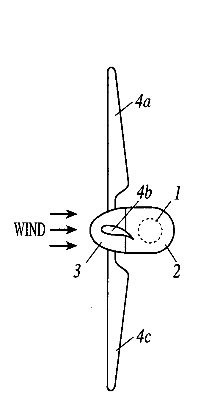
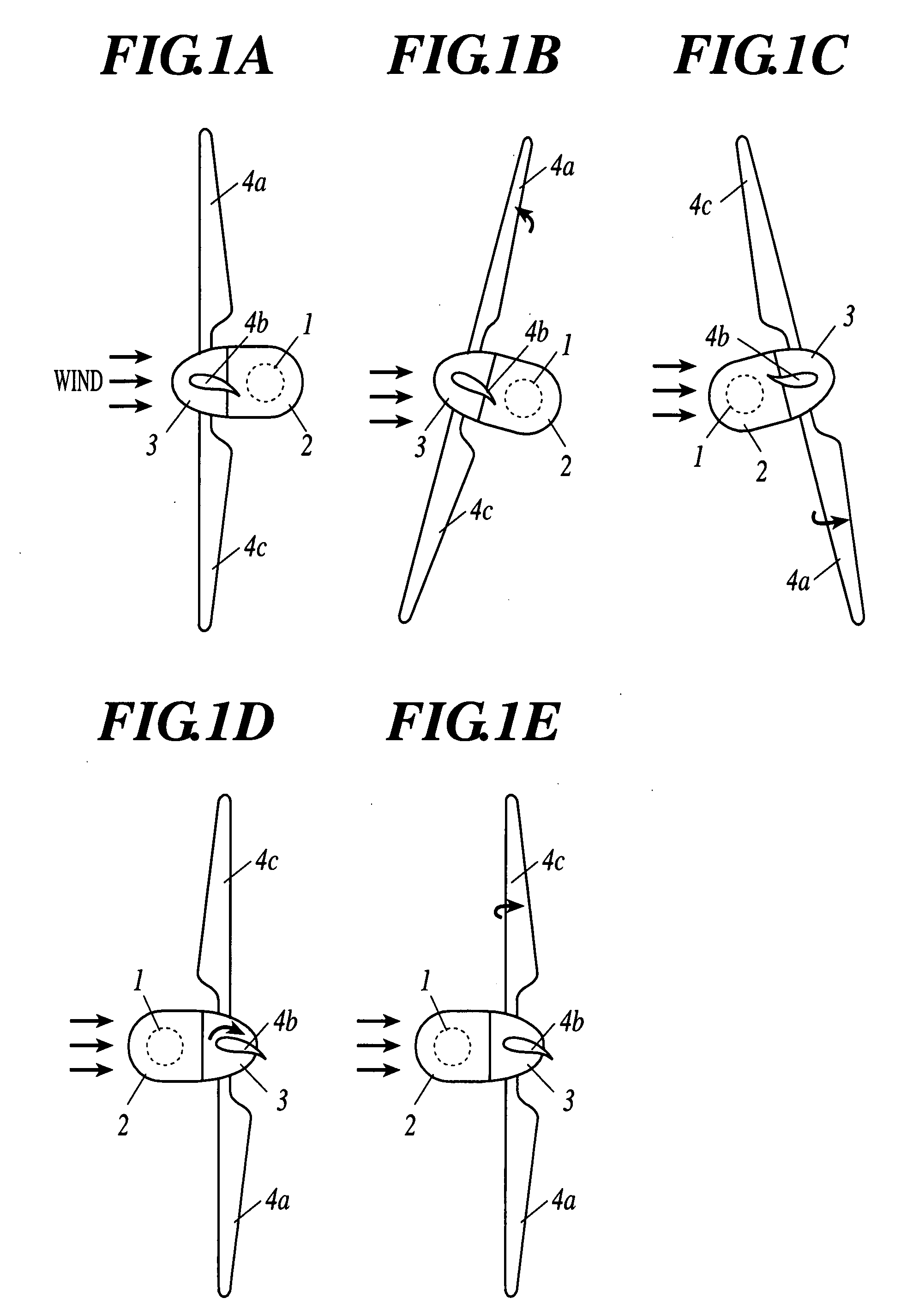
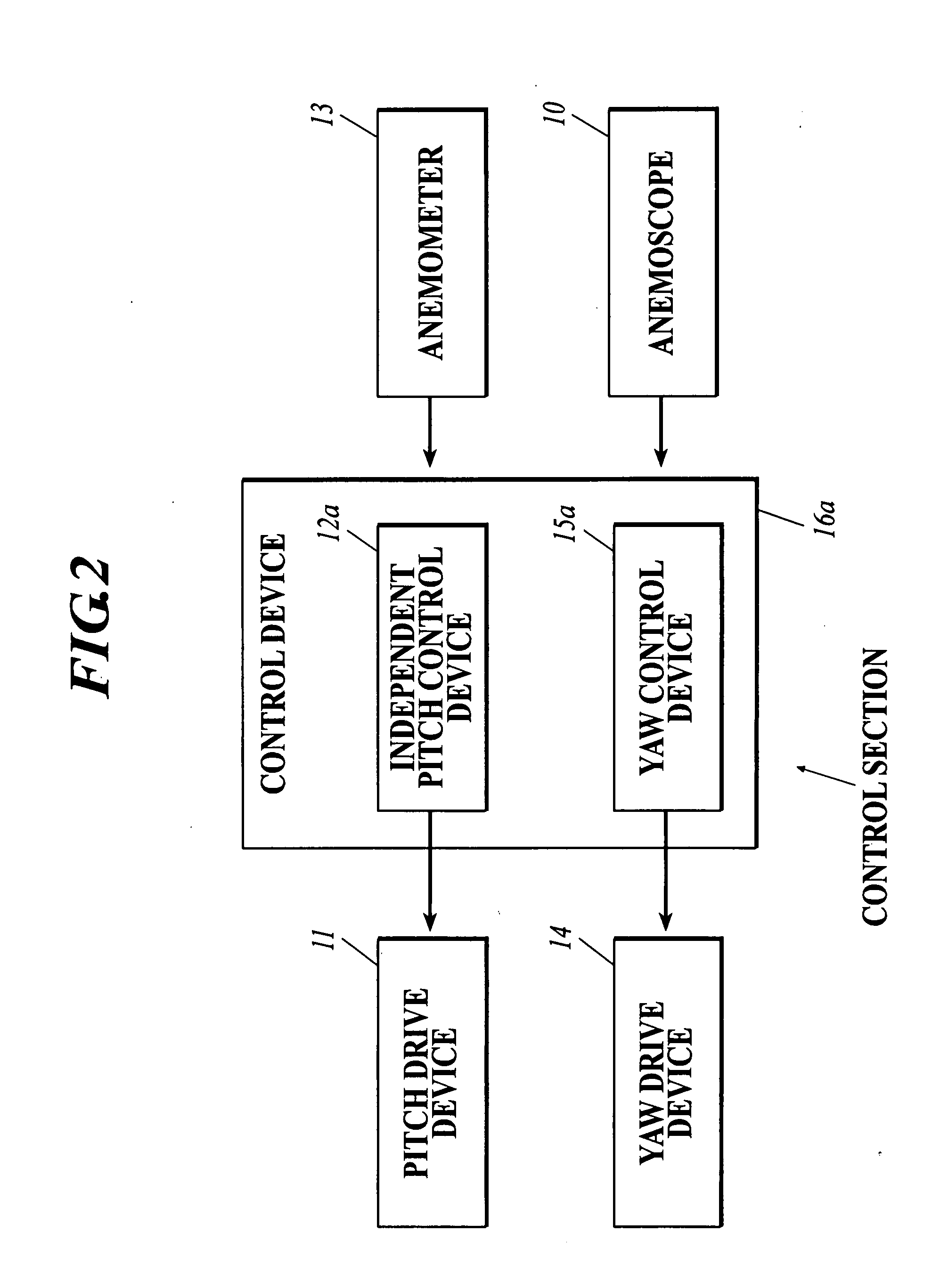
[0111]FIG. 1 is a plan view showing the up-wind type horizontal axis wind turbine of the first embodiment of the present invention when the wind turbine is seen from the upper part thereof. FIG. 2 is a block diagram showing the parts related to the present case in the configuration of a control section mounted on the up-wind type horizontal axis wind turbine of the first embodiment of the present invention.

[0112]As shown in FIG. 1, the horizontal axis wind turbine of the present embodiment is composed of a tower 1, a nacelle 2, a hub 3, and three blades 4a-4c.

[0113]The nacelle 2 supports a rotor composed of the hub 3 and the blades 4a-4c with the main shaft (not shown) of the nacelle 2, which main shaft is connected to the hub 3. The tower 1 supports the nacelle 2 with the yaw rotation thereof being free.

[0114]Moreover, a not-shown anemometer and a not-shown anemosco...

second embodiment

[0143]Next, the up-wind type horizontal axis wind turbine of the second embodiment of the present invention is described.

[0144]FIG. 12 is a plan view showing the up-wind type horizontal axis wind turbine of the second embodiment of the present invention when the wind turbine is seen from the upper part thereof.

[0145]As shown in FIG. 12, the horizontal axis wind turbine of the present embodiment includes the tower 1, the nacelle 2, the hub 3, and three blades 4a-4c.

[0146]The nacelle 2 supports the rotor composed of the hub 3 and the blades 4a-4c with the main shaft (not shown) of the nacelle 2, which main shaft is connected to the hub 3. The tower 1 supports the nacelle 2 with the yaw rotation thereof being free.

[0147]Moreover, a not-shown anemometer and a not-shown anemoscope are attached on the outer surface of the nacelle 2.

[0148]Not-shown power transmission devices such as the speed-increasing gear, the generator, and the main shaft brake are housed inside the nacelle 2, and the...

third embodiment

[0184]Next, the up-wind type horizontal axis wind turbine of the third embodiment of the present invention is described.

[0185]FIG. 14 is a plan view showing the up-wind type horizontal axis wind turbine of the third embodiment of the present invention when the wind turbine is seen from the upper part thereof. FIG. 15 is a block diagram showing the configuration of a control section mounted on the up-wind type horizontal axis wind turbine of the third embodiment of the present invention.

[0186]As shown in the FIG. 14, the horizontal axis wind turbine of the present embodiment is composed of the tower 1, the nacelle 2, the hub 3, and three blades 4a-4c.

[0187]The nacelle 2 supports a rotor composed of the hub 3 and the blades 4a-4c with the main shaft (not shown) of the nacelle 2, which main shaft is connected to the hub 3. The tower 1 supports the nacelle 2 with the yaw rotation thereof being free.

[0188]Moreover, a not-shown anemometer and a not-shown anemoscope are attached on the ou...


PUM


Abstract

Disclosed a horizontal axis wind turbine including: a rotor; a nacelle; a tower; an independent pitch control device; and a yaw control device, wherein the horizontal axis wind turbine is an up-wind type one including a waiting mode, wherein (1) the independent pitch control device performs a first step of changing all the blades to be in feathering states when the wind speed exceeds the predetermined value, a second step of changing the blades to be in reverse feathering states one by one sequentially, and a third step of holding all the blades in the reverse feathering states, and (2) the yaw control device controls a yaw brake to take a braking value allowing the yaw rotation when the wind speed exceeds the predetermined value, wherein the rotor is allowed to swing a leeward of the tower by executing the control operations (1) and (2) as the waiting mode.

Description

TECHNICAL FIELD[0001]The present invention relates to the waiting of an up-wind type horizontal axis wind turbine at the time of a windstorm.BACKGROUND OF THE INVENTION[0002]As is generally known, the so-called horizontal axis wind turbine has widely been put to commercially practical use. A general horizontal axis wind turbine is composed of a rotor, in which at least two blades are attached to a hub in a radial manner; a nacelle, which supports the rotor through the main shaft which is connected to the hub and extends substantially in the horizontal direction; and a tower, which is installed in substantially the vertical direction and supports the nacelle in the manner capable of performing a yaw rotation.[0003]In addition, it has conventionally been performed to provide the horizontal wind turbine with control means such as yaw drive means capable of freely performing the drive control of the yaw rotation of the nacelle, a yaw brake to put a brake on the yaw rotation, and a main ...

Claims


Application Information

Patent Timeline
IPC IPC(8): F03D7/04
CPCF03D7/0212F03D7/0224F03D7/024F03D7/0244Y02E10/723F03D7/042F05B2260/74F05B2260/90F05B2260/901F03D7/0268Y02E10/72
Inventor YOSHIDA, SHIGEO
Owner HITACHI LTD
Why Eureka
Try Eureka