Anode exhaust recycle system

a technology of anode exhaust and recycle system, which is applied in the direction of fuel cell systems, cell components, electrical devices, etc., can solve the problems of increasing the size of the fuel stack, the formidable entry etc., and achieves the effect of increasing the efficiency of the fuel cell system of the invention, increasing the utilization rate of total fuel, and high efficiency of the fuel cell system

Inactive Publication Date: 2009-02-19
SAINT GOBAIN CERAMICS & PLASTICS INC
View PDF15 Cites 6 Cited by
  • Summary
  • Abstract
  • Description
  • Claims
  • Application Information

AI Technical Summary

Benefits of technology

[0012]With the present invention for recycling anode exhaust, total fuel utilization can be increased, potentially near 100% fuel utilization. As such, the efficiency of the fuel cell system of the invention can be increased, compared to one that does not have a separator to recycle anode exhaust. This high efficiency of the fuel cell system can in turn allow to use a relatively small sized fuel stack. The fuel cell systems of the invention can be used in various applications, for example, to generate power and / or generating hot water.
[0013]Typically, in order to produce hydrogen gas from hydrocarbon fuel sources, such as natural gas, the fuel sources need to be reformed or pre-reformed using an oxygen source, such as steam and / or oxygen gas, to prevent elemental carbon formation. Steam has often been used in the art. To generate such steam, a boiler or steam generator is generally required, which makes the fuel cell system more complex and large in scale. In addition, a water purifying system is often further required to protect catalysts. In contrast, in the present invention, substantially pure hot water (steam) is recycled, and thus, extensive water treatment units, and steam generators or boilers, generally are not necessary, thereby simplifying the fuel cell system.

Problems solved by technology

Despite the advantages of clean and quiet power generation, fuel cell systems have faced a number of formidable market entry issues resulting from product immaturity, over-engineered system complexity, fuel efficiency, etc.
However, these approaches typically result in increases in the size of the fuel stack.

Method used


Image

  • Anode exhaust recycle system
  • Anode exhaust recycle system
  • Anode exhaust recycle system

Examples


Embodiment Construction

[0017]The foregoing will be apparent from the following more particular description of example embodiments of the invention, as illustrated in the accompanying drawings in which like reference characters refer to the same parts throughout the different views. The drawings are not necessarily to scale, emphasis instead being placed upon illustrating embodiments of the present invention.

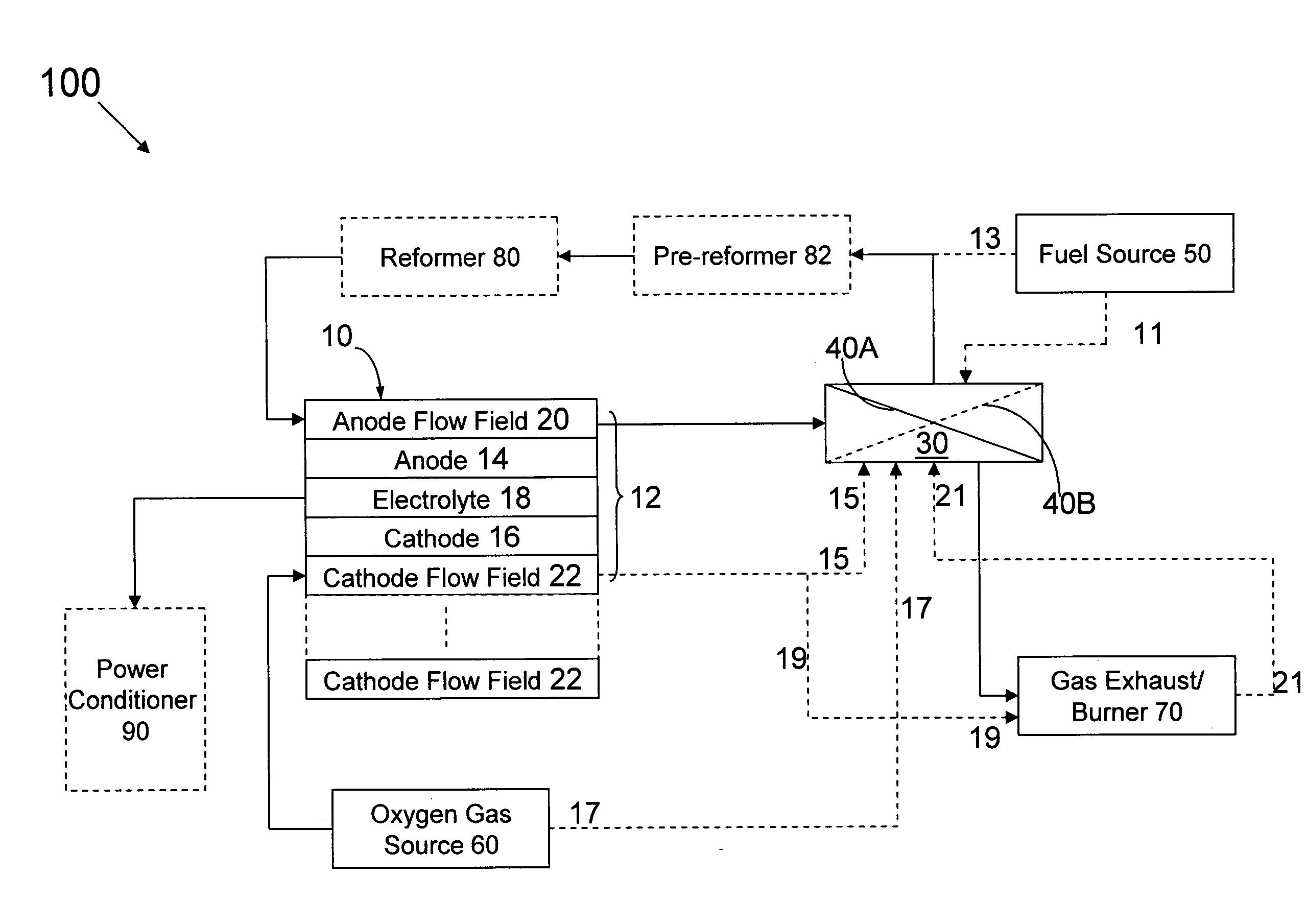
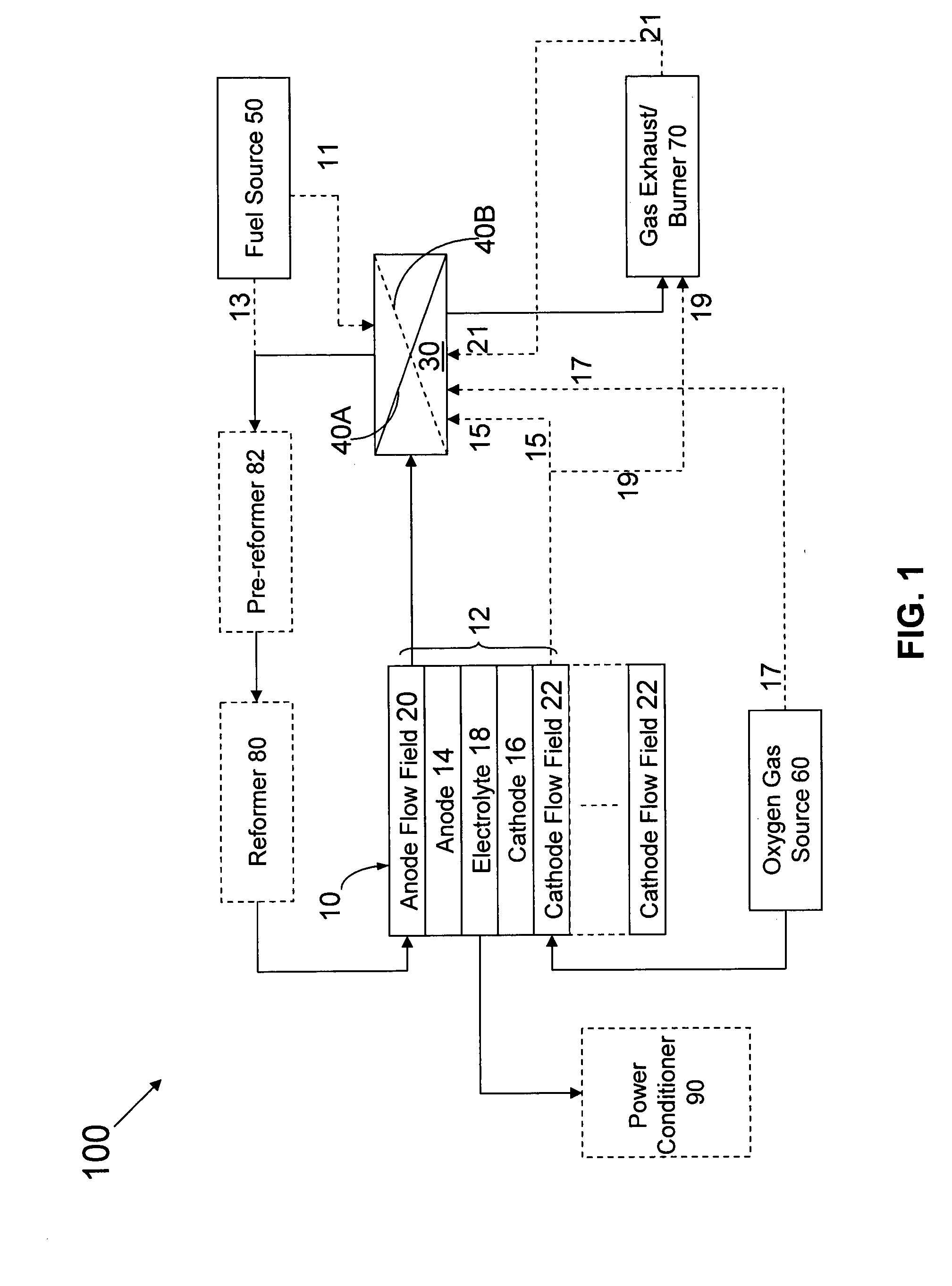
[0018]FIG. 1 shows one embodiment of the fuel cell systems of the invention, fuel cell system 100. Fuel cell system 100 includes fuel cell stack 10, separator 30, fuel source 50, oxygen gas source 60 and gas exhaust 70. Fuel cell stack 10 includes at least one fuel cell 12. Fuel cell 12 includes anode 14, cathode 16 and electrolyte 18. Anode 14 is in fluid communication with fuel source 50, such as H2 gas or a natural gas which can be converted into H2, optionally via anode flow field 20. Cathode 16 is in fluid communication with oxygen gas source 60, such as air, optionally via cathode flow field 22. ...


PUM

PropertyMeasurementUnit
permeableaaaaaaaaaa
selectively permeableaaaaaaaaaa
chemical energyaaaaaaaaaa

Abstract

A fuel cell system includes a fuel cell stack including at least one fuel cell and a separator. Each fuel cell includes a cathode, an anode and an electrolyte between the cathode and the anode. The separator includes a membrane, and a housing defining an anode exhaust inlet, a recycled gas outlet and an exhaust gas outlet. The anode exhaust inlet and the recycled gas outlet are independently in fluid communication with the anode. The housing and the membrane defines at least in part a first chamber that is in fluid communication with the anode exhaust inlet, and a second chamber. In one embodiment, the membrane is an H2-gas permeable membrane, the recycled gas outlet is in fluid communication with the second chamber, and the exhaust gas outlet is in fluid communication with the first chamber. In another embodiment, the membrane is a CO2-gas permeable membrane, the recycled gas outlet is in fluid communication with the first chamber, and the exhaust gas outlet is in fluid communication with the second chamber.

Description

RELATED APPLICATION[0001]This application claims the benefit of U.S. Provisional Application No. 60 / 963,952, filed on Aug. 8, 2007. The entire teachings of the above application are incorporated herein by reference.BACKGROUND OF THE INVENTION[0002]Fuel cells can offer potentially clean, quiet and efficient power generation. Unlike thermal energy based engines, fuel cells use an electrochemical or battery-like process to convert the chemical energy associated with the conversion of hydrogen gas into water. Typically, in fuel cells, hydrogen gas and oxygen gas are fed into the anode and cathode of the fuel cell, respectively. At the anode, the hydrogen gas is electrochemically dissociated into hydrogen ions (H+) and free electrons (e−). The electrons flow out of the anode through an external electrical circuit. In polymer electrolyte membrane (PEM) fuel cells, in general, hydrogen ions (H+) formed at the anode flow to the cathode through the PEM electrolyte. At the cathode, oxygen gas...

Claims


Application Information

Patent Timeline
Patent Type & Authority Applications(United States)
IPC IPC(8): H01M4/00
CPCH01M8/0612Y10T29/49108Y02E60/50H01M8/0687H01M8/04097
Inventor QI, CHUNMING
Owner SAINT GOBAIN CERAMICS & PLASTICS INC
Why Eureka
Try Eureka