Intra-Ocular Implant

a technology of intraocular implants and ocular arteries, applied in the field of intraocular implants, can solve the problems of limiting the visual improvement that can be achieved using the implant, difficult or impossible to manufacture such implants made of a single piece, and complicated manufacturing, so as to facilitate the bringing of objects into focus, change the curvature, position or optical properties

Inactive Publication Date: 2009-02-19
LIPSHITZ ISAAC +1
View PDF15 Cites 16 Cited by
  • Summary
  • Abstract
  • Description
  • Claims
  • Application Information

AI Technical Summary

Benefits of technology

[0027]Another object of the invention is to disclose an intra ocular implant. The implant comprises (a) a body member; and, (b) an optical arrangement comprising at least one mirror and, especially an arrangement comprising at least one member of a group consisting of lens, prisms, diffractive optics elements, liquid crystal elements, Fresnel pri

Problems solved by technology

U.S. Pat. No. 4,759,761 describes an implant creating one magnified image on the retina, but the implant as shown is smaller than the pupil opening, and this limits the visual improvement that can be achieved using the implant.
The mirrors are embedded inside the implant making them much more complicated to manufacture than mirrors that are attached or vaporized on the surface of the implant.
Depending on the configuration of the mirrors in those implants, it is difficult or impossible to manufacture such implants made of a single piece.
Those implants c

Method used


Image

  • Intra-Ocular Implant
  • Intra-Ocular Implant
  • Intra-Ocular Implant

Examples


Embodiment Construction

[0032]In order to understand the invention and to see how it may be implemented in practice, preferred embodiments will now be described, by way of non-limiting example only, with reference to the accompanying drawings in which

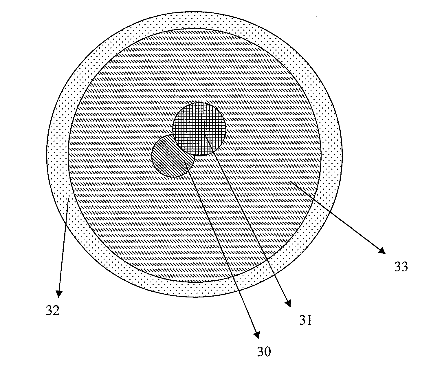
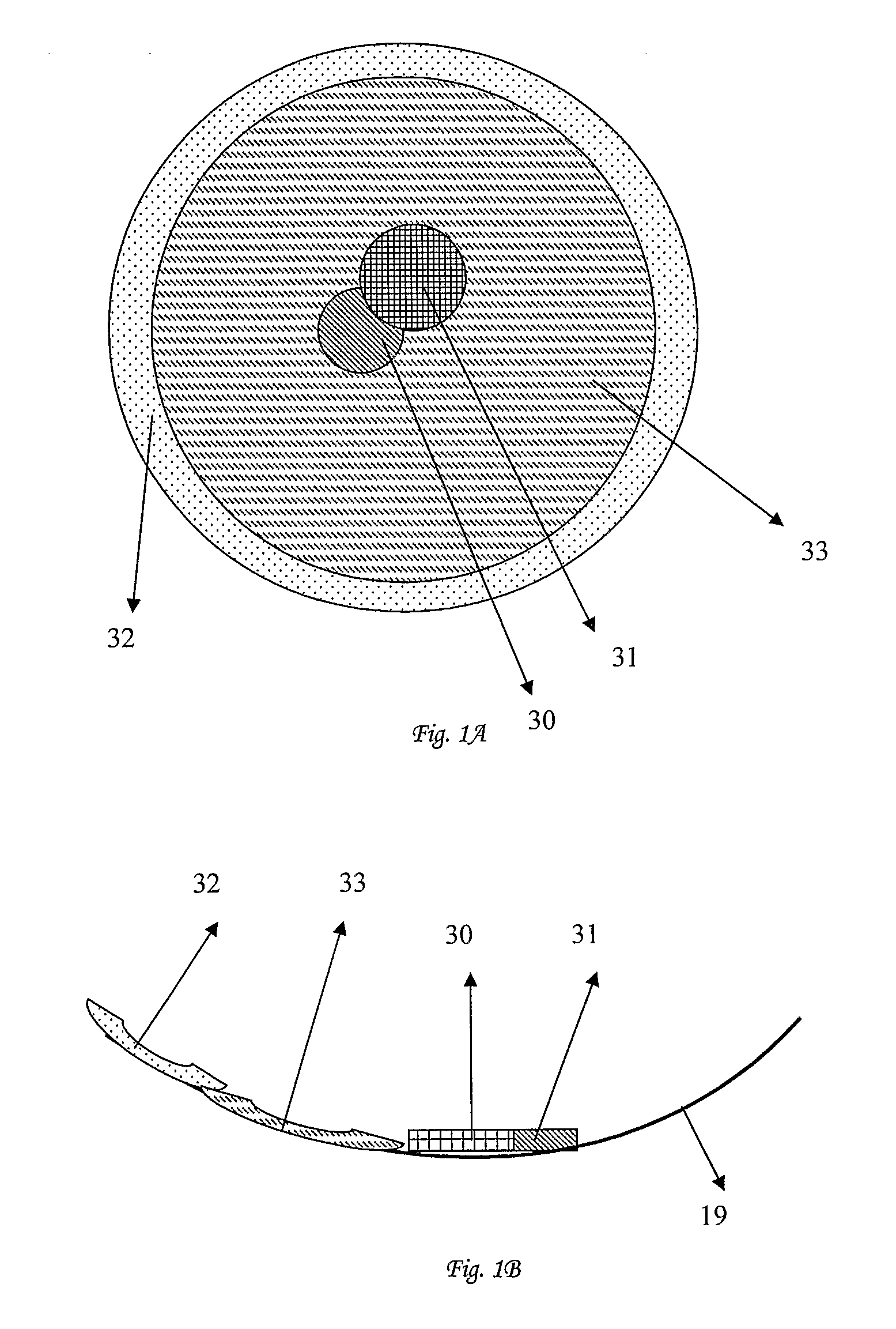
[0033]FIG. 1A presents a schematic vertical illustration of the image received on the retina according to one embodiment of the present invention;

[0034]FIG. 1B presents a schematic side view of the image received on the retina according to one embodiment of the present invention;

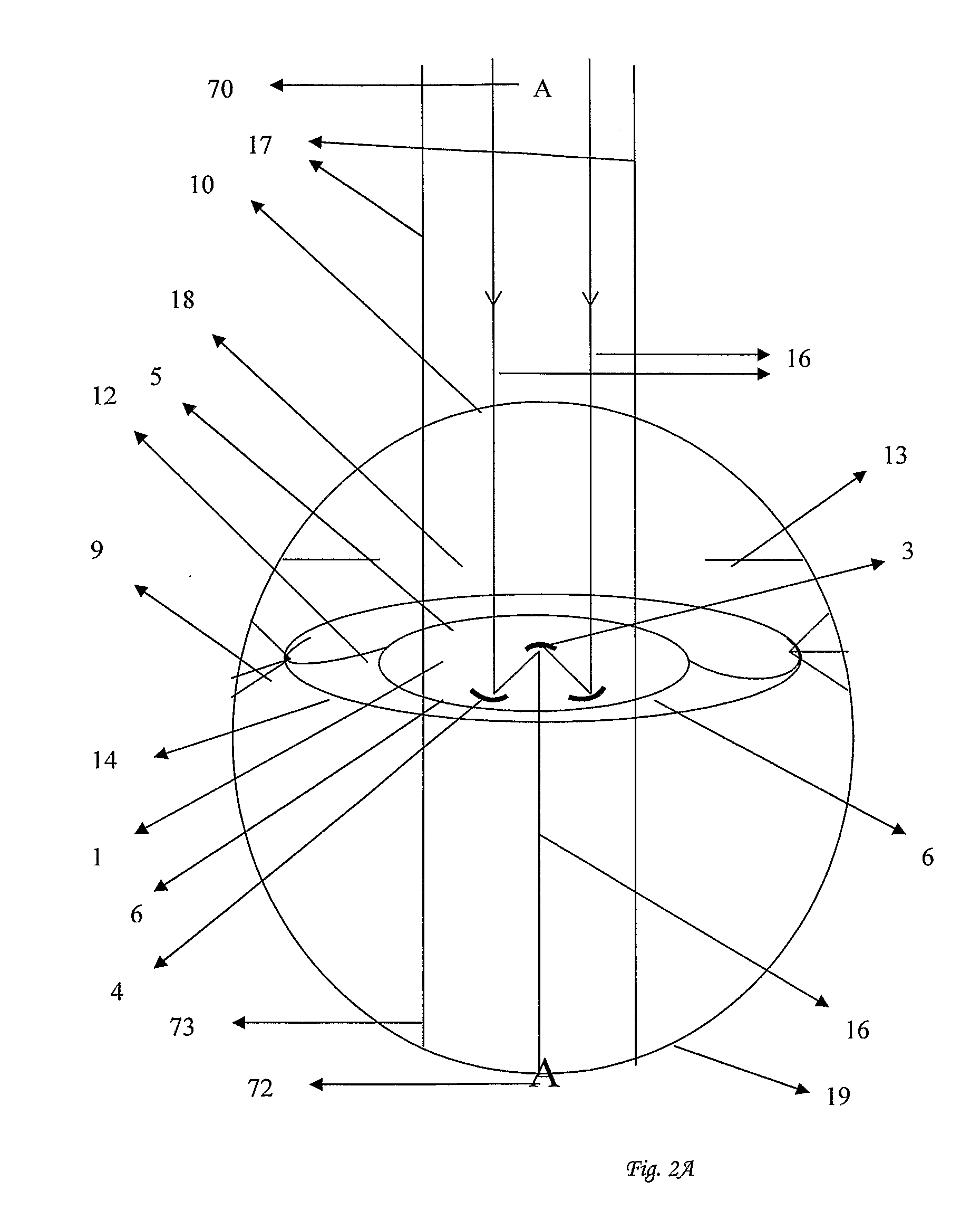
[0035]FIG. 2A presents a schematic illustration of perceivable color differences received on the retina according to one embodiment of the present invention;

[0036]FIG. 2B presents a schematic illustration of perceivable color differences received on the retina according to another embodiment of the present invention;

[0037]FIG. 3 presents a schematic illustration of overlap and / or illumination reduction according to one embodiment of the present invention.

[0038]FIG. 4 presents a schemat...


PUM


Abstract

An intra ocular implant consisting of optical elements, adapted to forming images on the retina, especially useful in treating presbyopic patients, patients with AMD, patients with other diseases of the retina, and patients in which future development of retinal disorders may occur. An intra ocular implant wherein at least one mirror is operationally connected to the action of the ciliary muscle or its effect on the zonules and capsule of the natural lens; and wherein the mirror is adapted to change curvature, position or optical properties, such that bringing a plurality of objects at different distances into focus is facilitated in presbyopic patients. A lens assembly comprising an intra ocular lens and, an adjustable external or contact lens comprising at least in part of light polarizing material; the assembly at least partially polarizes at least part of the central visual field, at least part of the peripheral visual field or both in any angle.

Description

FIELD OF THE INVENTION[0001]This invention relates to an intra-ocular implant useful in improving vision in patients suffering from AMD and other retinal diseases and presbyopia.BACKGROUND OF THE INVENTION[0002]This new disclosure is an improvement over the teaching of U.S. Pat. No. 4,759,761 by Portnoy and U.S. Pat. Nos. 6,902,577, 6,920,399, 7,008,448 by Lipshitz et al. These patents disclose an intra-ocular implant that contains mirrors for modifying central vision for patients who suffer from retinal diseases such as macular degeneration (AMD) and for the treatment of presbyopia. The above-mentioned patents deal with changing (increasing or decreasing) the size of an object on the central retina as needed for AMD and other retinal patients. The above-mentioned patents suffer from several shortcomings.[0003]U.S. Pat. No. 4,759,761 describes an implant creating one magnified image on the retina, but the implant as shown is smaller than the pupil opening, and this limits the visual...

Claims


Application Information

Patent Timeline
IPC IPC(8): A61F2/16
CPCA61F2/1613G02B17/0808A61F2/1654G02C7/088A61F2/1648G02B17/086
Inventor LIPSHITZ, ISAACLIPSHITZ, YARIV
Owner LIPSHITZ ISAAC
Why Eureka
Try Eureka