
Capacitor and method of manufacturing the same

a technology of capacitors and manufacturing methods, applied in the direction of capacitors, capacitor housing/encapsulation, capacitor terminals, etc., can solve the problems of unexpectedly large mounting space, cumbersome work, and inability to downsize capacitor units, so as to achieve advantageously reduce resistance and facilitate downsizing of capacitor units.

Inactive Publication Date: 2009-02-26
PANASONIC CORP
View PDF9 Cites 2 Cited by
  • Summary
  • Abstract
  • Description
  • Claims
  • Application Information

AI Technical Summary

Benefits of technology

This design achieves a significant reduction in resistance and an increase in capacity, allowing for more compact capacitor units with improved electrical performance.

Problems solved by technology

This requires a cumbersome work, and coupling spaces h1 and h2 must be prepared at both the ends, so that an unexpectedly large mounting space is needed.
As a result, the capacitor unit cannot be downsized.
This method is thus not always good for a capacitor unit formed by coupling plural capacitors together.
However, it is difficult to downsize the conventional capacitors because of the structure of terminal plate 42 (or terminal plate 45).
In recent years, capacitors have been required to be downsized and yet to have a greater capacity, so that a greater height of capacitor element 40 cannot be allowed amid the environment where the height of capacitors are limited.
As a result, it is extremely difficult to increase the capacity of capacitors as well as decrease the resistance thereof.

Method used


Image

  • Capacitor and method of manufacturing the same
  • Capacitor and method of manufacturing the same
  • Capacitor and method of manufacturing the same

Examples


embodiment 1

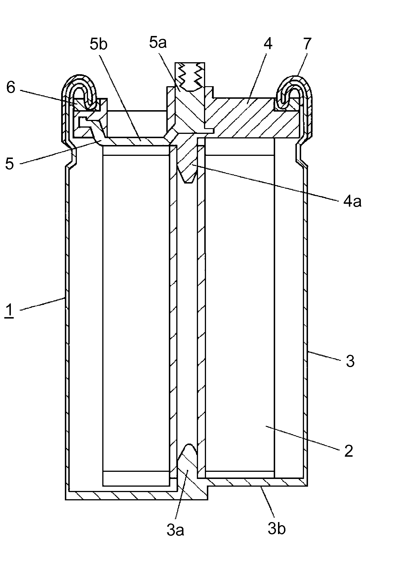
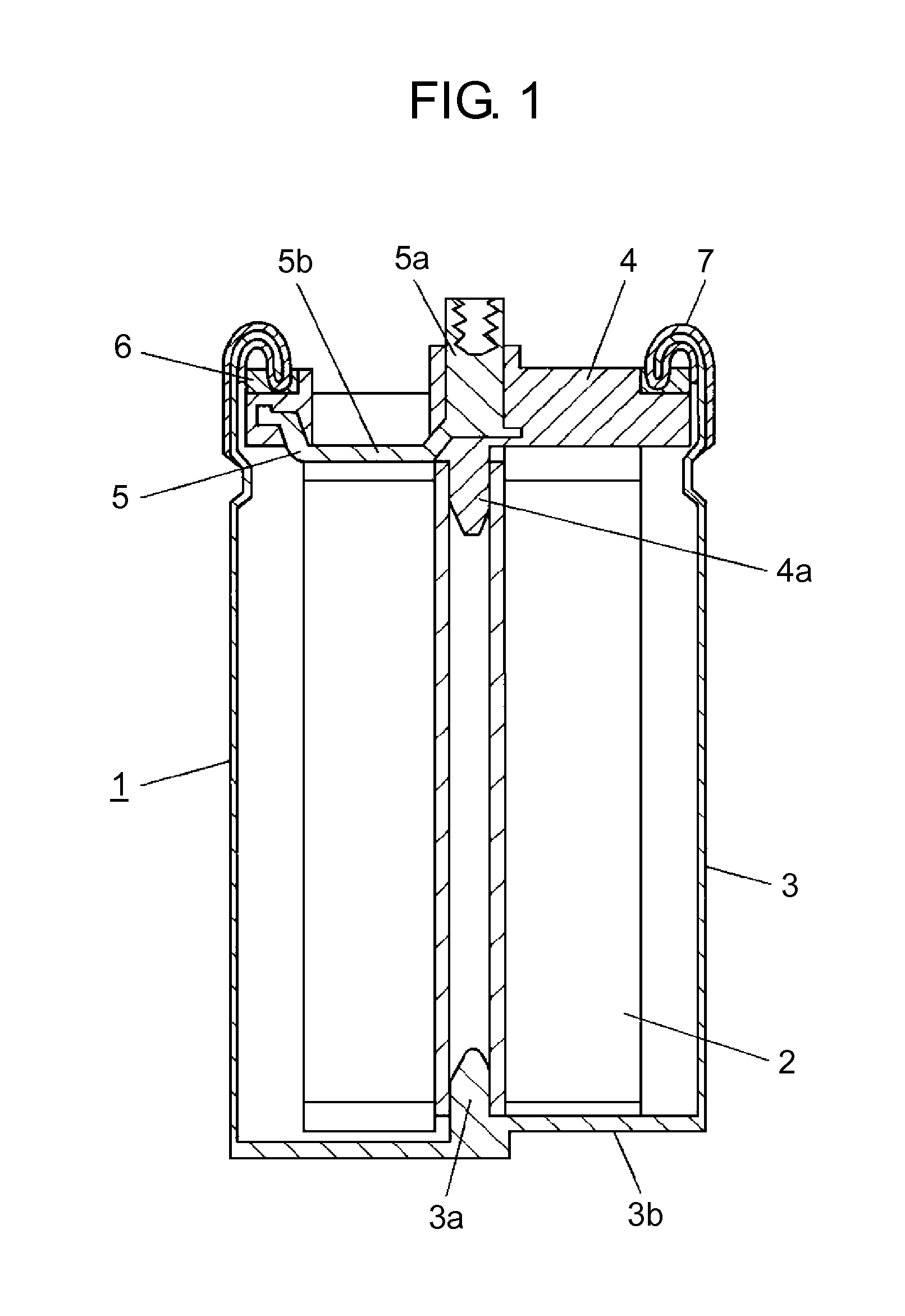
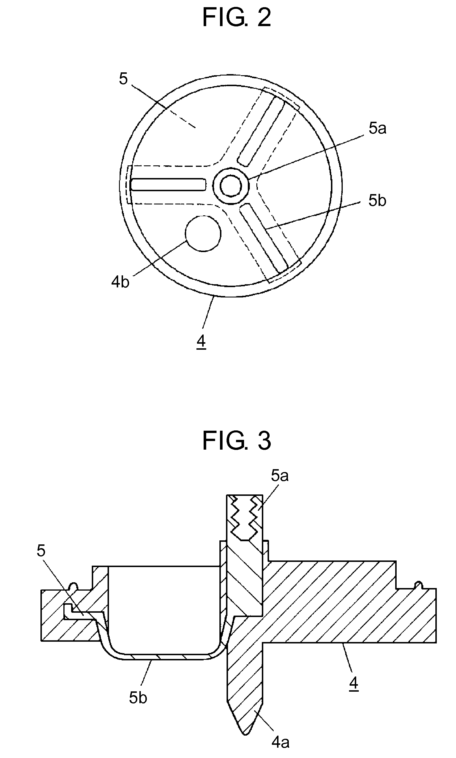
[0071]FIG. 1 shows a sectional view illustrating a structure of a capacitor in accordance with the first embodiment of the present invention. FIG. 2 shows a plan view of a terminal plate to be used in the capacitor. FIG. 3 shows a sectional view of the terminal plate. FIG. 4 shows a plan view of a terminal slip to be insert-formed into the terminal plate. In FIGS. 1-4, capacitor 1 includes capacitor element 2, which has a pair of electrodes (not shown) forming a polarized electrode layer of which major ingredients are activated carbon and binder. The polarized electrode layer is formed on a current collecting unit made of aluminum foil such that the current collecting unit exposes itself at its one end. The pair of electrodes is formed by rolling the exposed section of the current collecting unit such that the exposed section is oriented in opposite directions and a separator (not shown) is disposed between the exposed sections oriented oppositely. The anode and the cathode of the p...

embodiment 2

[0083]The second embodiment presents a capacitor unit formed by linking a plurality of the capacitors to each other in accordance with the first embodiment. Similar elements to those used in the first embodiment have the same reference characters, and the descriptions thereof are omitted, while only different ones are described hereinafter with reference to FIG. 5.

[0084]FIG. 5 shows a front view illustrating a structure of a capacitor unit in accordance with the second embodiment of the present invention. Capacitor 1 has the same structure as the one in accordance with the first embodiment, and includes terminal 5a connected to an anode of a capacitor element (not shown). Capacitor 1 is adjacent to capacitor 8 which has terminal 9a connecting to a cathode of a capacitor element.

[0085]Capacitor 1 is brought out its anode from terminal 5a and its cathode from its metal housing. Capacitor 8 has its anode brought out from its metal housing and its cathode from terminal 9a. The metal hou...

embodiment 3

[0087]The third embodiment presents a case where the capacitor element in accordance with the first embodiment has a coupling method for its anode and cathode that is partly different than the method demonstrated in embodiment 1. Other than this point, this third embodiment remains unchanged from embodiment 1, and similar elements to those in embodiment 1 have the same reference characters and the descriptions thereof are omitted here. Elements different from embodiment 1 are demonstrated hereinafter with reference to FIGS. 6A, 6B, and 7.

[0088]FIGS. 6A and 6B show sectional views illustrating structures of essential parts of capacitors in accordance with the third embodiment of the present invention. Capacitor element 12 is formed of the following elements:[0089]anodes 15 having polarized electrode layer 14a formed on the surface of current collecting unit 13a made of aluminum foil;[0090]cathodes 16 having polarized electrode layer 14b formed on the surface of current collecting uni...


PUM


Abstract

A capacitor is provided to overcome the following problem: when plural capacitors are linked, a large coupling space is required because an anode and a cathode are brought out through the opposite ends, so that downsizing of the capacitor is difficult. The capacitor also allows easy electrical and mechanical coupling, reducing the required coupling space and unnecessary resistance. According to a structure of the capacitor, capacitor element (2) is enclosed in mechanical housing (3) having an opening sealed by terminal plate (4). Terminal slip (5), which includes rib (5b) to be coupled to one of the anode and the cathode of capacitor element (2) and terminal (5a), is insert-molded into terminal plate (4). The other of the anode and the cathode is coupled to an inner bottom face of metal housing (3). The one of the anode and the cathode is brought out through terminal (5a), and the other of the anode and the cathode is brought out through metal housing (3), thus a lower resistance is expected. When plural capacitors (1) are linked together, the coupling space is reduced by half, so that downsizing is achieved.

Description

[0001]This application is a divisional application of application Ser. No. 10 / 595,043, which is a U.S. national phase application of PCT International Application PCT / JP2005 / 009641, filed May 26, 2005.TECHNICAL FIELD[0002]The present invention relates to capacitors to be used for regenerating batteries of hybrid cars and fuel-cell powered vehicles, or for a power-storing purpose, and it also relates to methods of manufacturing the same capacitors.BACKGROUND ART[0003]FIG. 23 shows a sectional view illustrating a structure of a conventional capacitor to be used for applications similar to the foregoing ones. Capacitor element 20 is formed by rolling the following members: a pair of electrodes in a polarized electrode layer formed on a current collecting unit made of aluminum foil are prepared with a separator disposed between the pair of electrodes, and each of the pair of electrodes protrudes in opposite directions. To be more specific in FIG. 23, an end of a first electrode of the p...

Claims


Application Information

Patent Timeline
Patent Type & Authority Applications(United States)
IPC IPC(8): H01G9/00H01G9/008H01G9/016H01G9/10H01G9/155H01G9/26
CPCH01G9/008Y10T29/417H01G9/10H01G9/00
Inventor MIURA, TERUHISASIMAMOTO, HIDEKIINOUE, TATEHIKOYOSHINO, TSUYOSHI
Owner PANASONIC CORP
Features
  • Generate Ideas
  • Intellectual Property
  • Life Sciences
  • Materials
  • Tech Scout
  • Unparalleled Data Quality
  • Higher Quality Content
  • 60% Fewer Hallucinations
Learn More