
Fiber optic position transducer with magnetostrictive material and position calibration process

a technology of magnetostrictive material and position transducer, which is applied in the direction of measuring device, instruments, sensor output conversion, etc., can solve the problems of reduced result precision, inability to serial multiplex, and mechanical alignment of light beams, and achieve high reliability and robust fiber optics

Inactive Publication Date: 2009-02-26
PETROLEO BRASILEIRO SA (PETROBRAS) +1
View PDF13 Cites 6 Cited by
  • Summary
  • Abstract
  • Description
  • Claims
  • Application Information

AI Technical Summary

Benefits of technology

The solution provides a robust, precise, and multiplexable position measurement system resistant to high pressures and temperatures, with simplified construction and extended dynamic range, capable of operating in aggressive environments without wear or electromagnetic interference.

Problems solved by technology

This presents a weakness, since the mirror can be displaced in relation to the fiber, leading to the need to mechanically align the light beam as well as problems related to the cleanliness of the optical surfaces (tip of the fiber and mirror).
Moreover, if dealing with transducers that must be located at the end of the fiber, serial multiplexing is not possible.
The high sensitivity to angular misalignment of the fiber optic line in relation to the surface is one disadvantage of transducers based on light intensity that even require a visually homogeneous target surface, with reduced result precision when the surface is less reflective.
Some applications already exist that use these magnetostrictive materials in the construction of devices for measuring magnetic field and torque, for example, but up until now, there are few that are large enough to use as position sensors.
By including the information from its optic specter, Fiber Bragg Grating Sensors supply an absolute measurement that is easily multiplexed, with applications where traditional sensing systems have shown to be inefficient.
Moreover, they are susceptible to electromagnetic interferences.

Method used


Image

  • Fiber optic position transducer with magnetostrictive material and position calibration process
  • Fiber optic position transducer with magnetostrictive material and position calibration process
  • Fiber optic position transducer with magnetostrictive material and position calibration process

Examples


Embodiment Construction

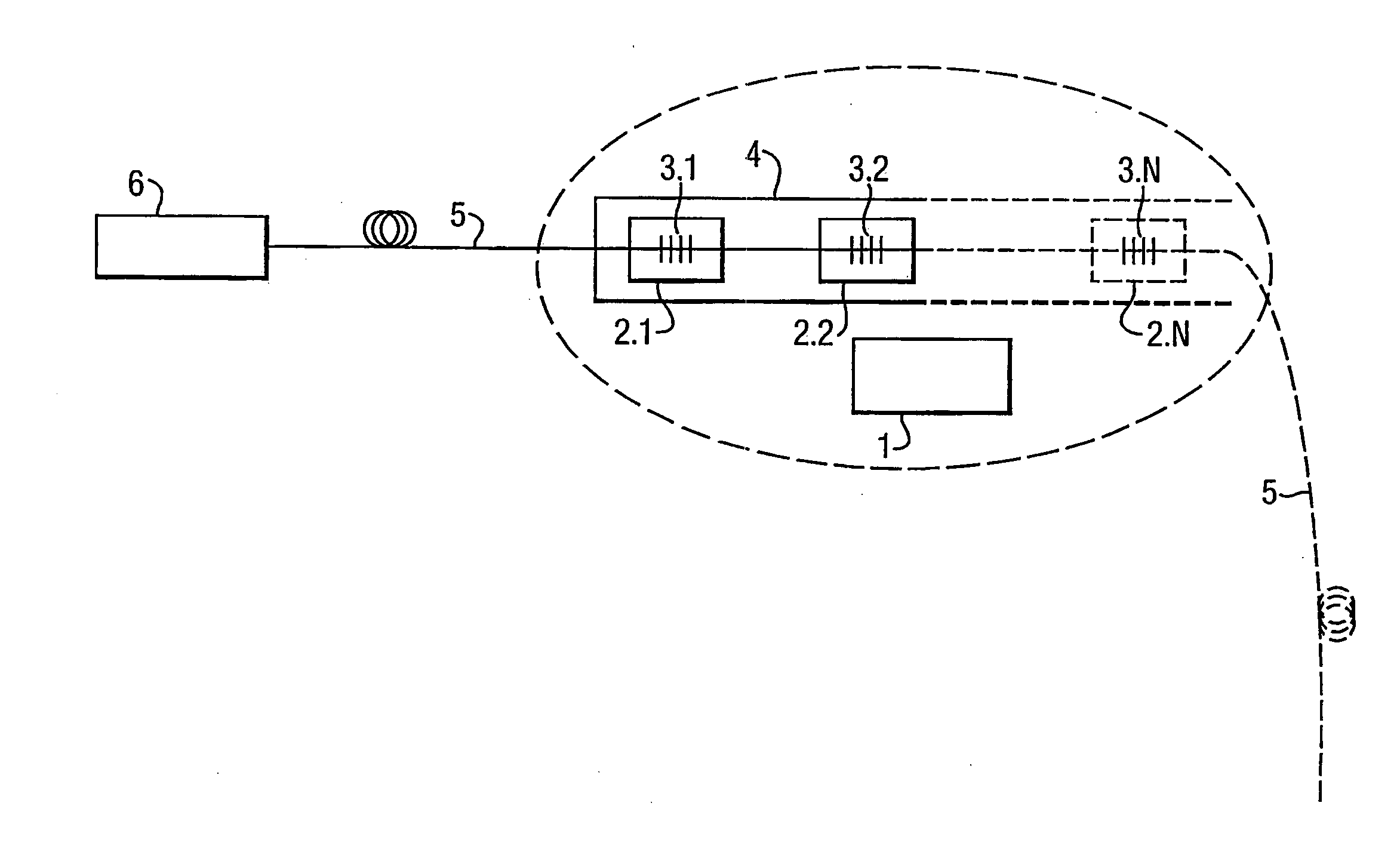
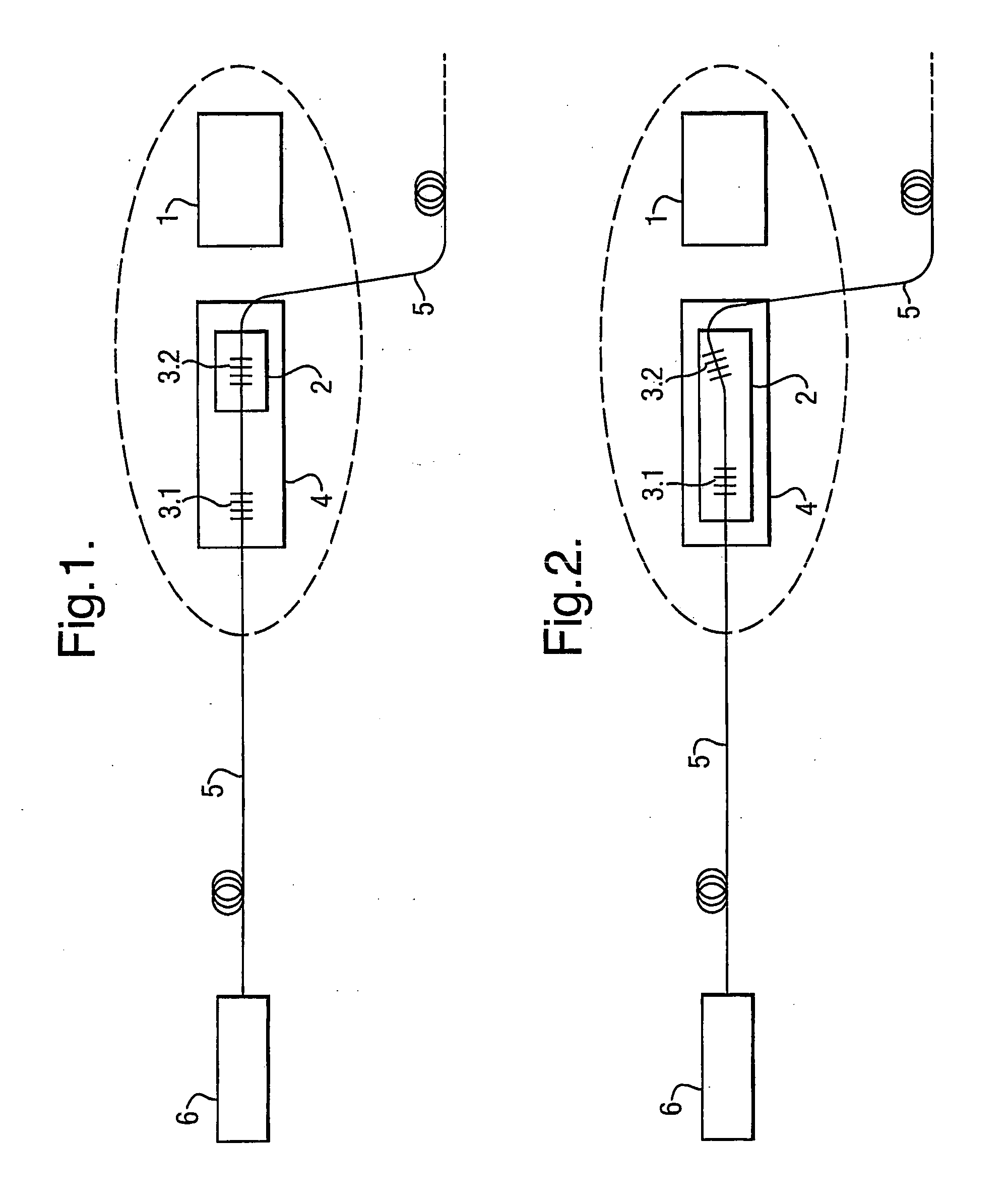
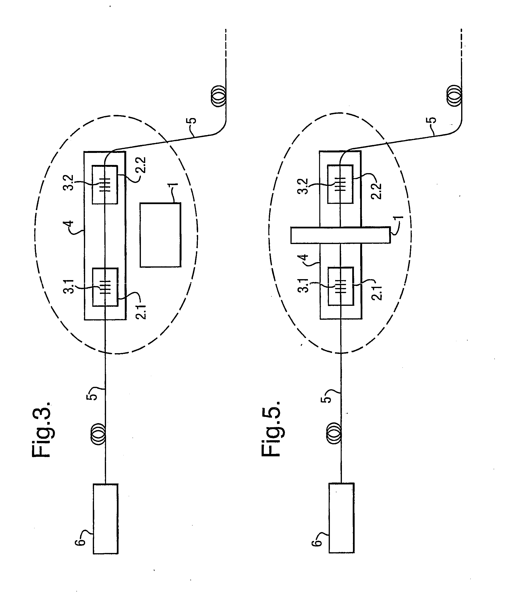
[0032]A detailed explanation is given of the fiber optic position transducer with magnetostrictive material and Fiber Bragg Grating Sensors in flow control valves (choke), suitable for use in onshore and offshore installations of deep wells.

[0033]It is a position transducer resistant to high pressures and temperatures, with high sensitivity, simple construction, compact, using Fiber Bragg Grating Sensors (FBG) with magnetostrictive material.

[0034]The principle upon which the present invention is based has to do with the relative displacement between a magnetic field source and a segment of magnetostrictive material, which is connected to one or more Fiber Bragg Grating Sensors. Changes in the relative position between a magnetic field source and a segment of magnetostrictive material cause changes in the size of this segment and, for this reason, in the sensor to which it is connected, which induces alterations in the wave lengths reflected by the Fiber Bragg Grating Sensors. Once t...


PUM


Abstract

Fiber optic position transducer that includes a magnetic or electromagnetic element, one or more segments of magnetostrictive material, Fiber Bragg Grating Sensors, a rod of material that is impenetrable to magnetic fields, optical fiber. One or more of the sensors is fixed upon a segment of magnetostrictive material, which is fixed to a rod, and may only be displaced longitudinally. The Fiber Bragg Grating Sensors have different wave lengths and are made of the same optical fiber. The magnetic or electromagnetic element included may be made of NdFeB (Neodymium Iron Boron) or metal alloys of TbDyFe (Terbium, Dysprosium and Iron), such as TX, Terphenol-D and others. It is applied to a control flow valve in an oil well, and it also refers to the calibration process of the position of the transducer.

Description

CROSS REFERENCE TO RELATED APPLICATION[0001]This application is a continuation of application Ser. No. 11 / 434,517, filed May 16, 2006, and is based upon and claims the benefit of, priority of, and incorporates by reference, the contents of Brazilian Patent Application No. PI 0501790-4 filed May 17, 2005.FIELD OF THE INVENTION[0002]The present invention refers to methods of measuring the position of equipment in deep wells in onshore and offshore installations. Specifically it is of application on flow control valves, called “choke”.DESCRIPTION OF THE STATE OF THE ART[0003]Some manufacturers have commercially developed fiber optic position transducers based on interferometry or light intensity. Fiso's position transducer falls into this first category, as described in the article, “Fiso'sWhite-Light Fabry-Perot Fiber-Optics Sensors”; Fiso Technologies Inc. The Philtec position transducer, presented in “Philtec Fiber optic Displacements Sensors”, Philtec Inc. 2002, currently uses meas...

Claims


Application Information

Patent Timeline
Patent Type & Authority Applications(United States)
IPC IPC(8): G02B6/00
CPCG01D5/485G01D5/35312G02B6/022G02B6/02195
Inventor ARIAS VIDAL, JOSE LUIZFREITAS, RICARDO MUNOZBARBOSA BRAGA, ARTHUR MARTINSGUEDES VALENTE, LUIS CARLOSOLIVEIRA BRUNO, ANTONIO CARLOSCARVALHO, HELIO RICARDO
Owner PETROLEO BRASILEIRO SA (PETROBRAS)
Learn More