Thrombectomy System and Method

a thrombosis and thrombosis technology, applied in the field of medical devices, can solve problems such as limb loss, stroke, brain damage, and death, and achieve the effects of reducing the risk of stroke, and improving the survival ra

Active Publication Date: 2009-02-26
TYCO HEALTHCARE GRP LP
View PDF18 Cites 154 Cited by
  • Summary
  • Abstract
  • Description
  • Claims
  • Application Information

AI Technical Summary

Problems solved by technology

These disorders are a major cause of morbidity and mortality in the United States.
Failure to re-establish blood flow can lead to the loss of limb, angina pectoris, myocardial infarction, stroke, compromised cognitive or neural function, or even death.
Occlusion of the venous circulation by thrombi leads to blood stasis, which can cause numerous problems.
The majority of pulmonary embolisms are caused by emboli that originate in the peripheral venous system although occlusions of the cerebrovasculature occur in millions of Americans yearly, often with catastrophic results.
Additionally, the use of a Fogarty catheter is problematic because of the great risk of damaging the interior lining of the vessel as the catheter is being withdrawn.
Balloon angioplasty is appropriate for treating vessel stenosis but is not effective for treating acute thromboemboli.
Unfortunately, thrombolysis typically takes hours to days to be successful.
The use of such removal devices can be difficult in at least some cases and sometimes unsuccessful.
A problem with the system of U.S. Pat. No. 5,102,415 is that the interaction between the balloon catheter and the leading edge of the catheter may tend to shear off portions of the obstruction.
This can cause obvious problems when working in sensitive vascular areas since pieces of the obstruction can migrate and cause further obstruction with adverse ischemic consequences.

Method used


Image

  • Thrombectomy System and Method
  • Thrombectomy System and Method
  • Thrombectomy System and Method

Examples


Embodiment Construction

[0035]The invention may be embodied in other specific forms without departing from its spirit or essential characteristics. The described embodiments are to be considered in all respects only as illustrative and not restrictive. The scope of the invention is therefore indicated by the appended claims rather than the foregoing description. All changes that come within the meaning and range of equivalency of the claims are to be embraced within their scope.

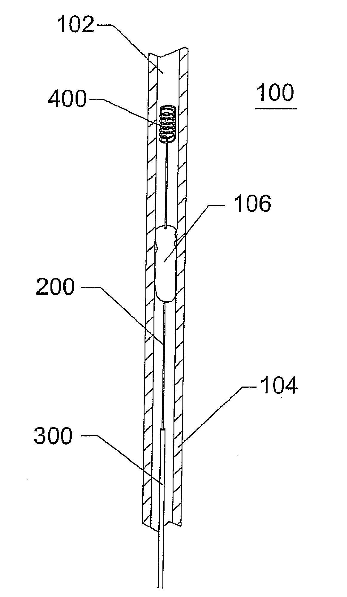
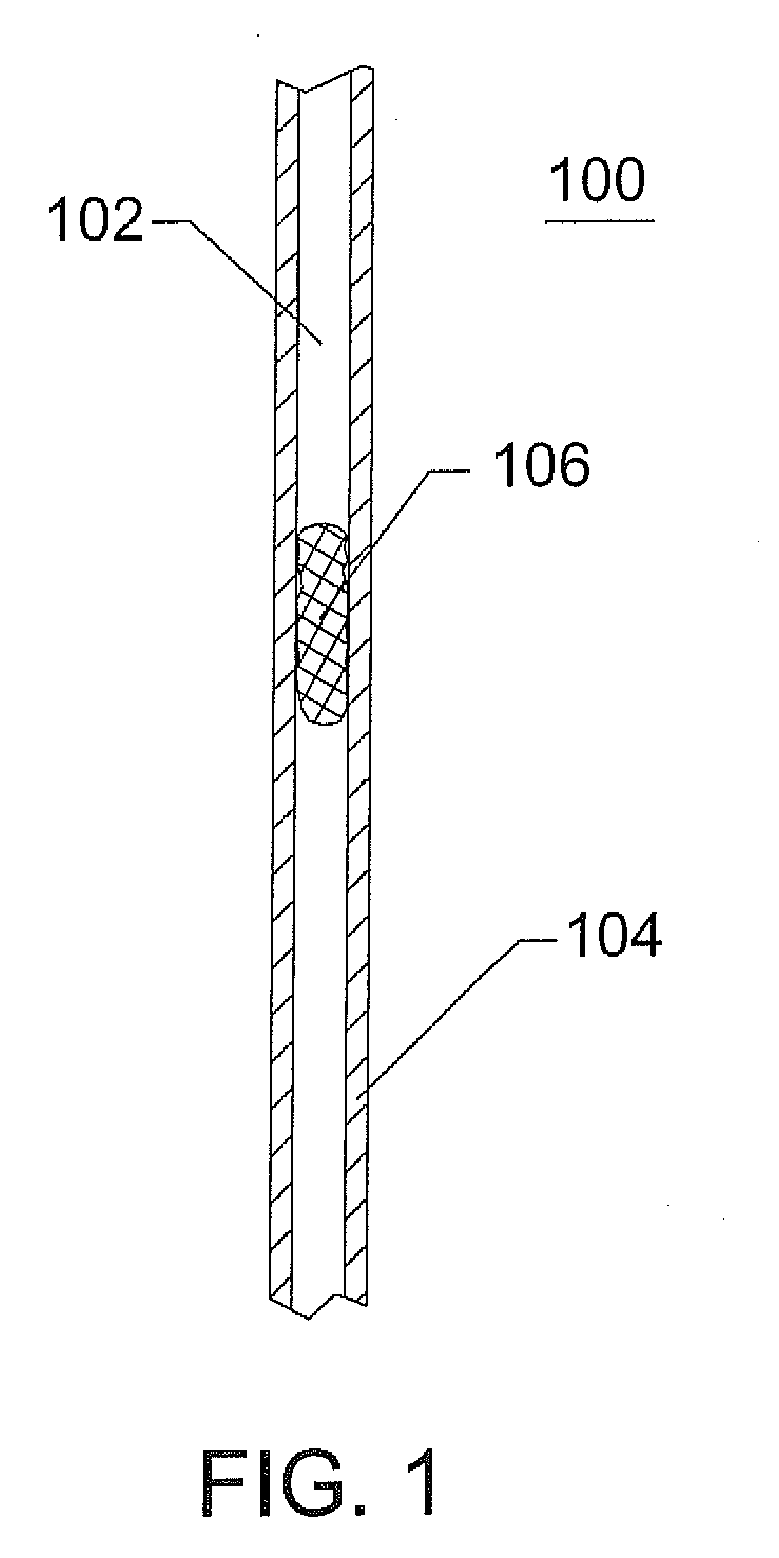
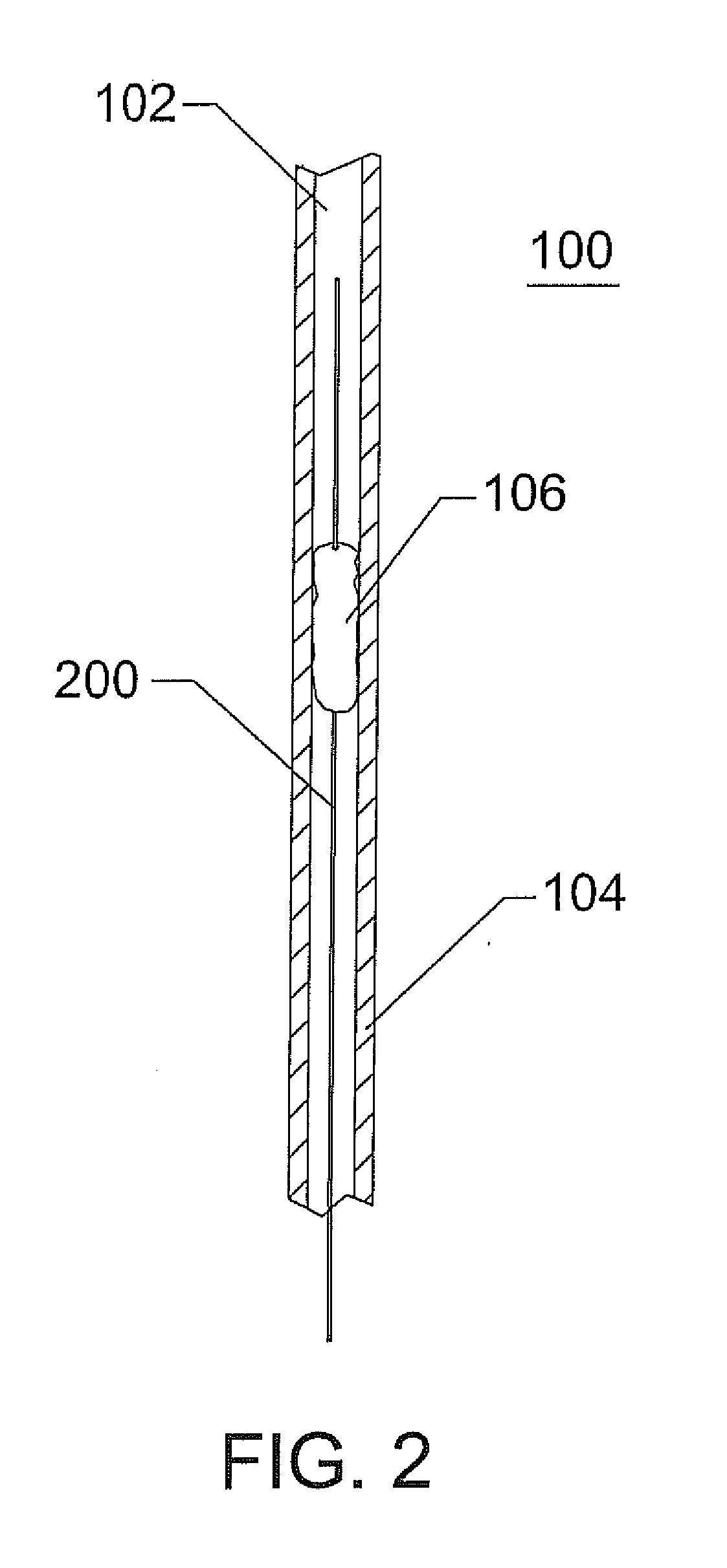
[0036]The present invention is directed to methods and devices for removing obstructions from blood vessels. The device may be used to retrieve and remove clots and other biological obstructions. The device may also be used to retrieve embolic coils and the like which have been misplaced or have migrated to an undesirable location.

[0037]In an embodiment of the invention, a catheter is advanced to the region of an obstruction. The obstruction can reside within a body vessel or lumen. The body vessel or lumen can be that of a human, m...


PUM


Abstract

Disclosed is a clot and foreign body removal system, including a catheter with at least one lumen. Located within the catheter is a clot capture wire that is connected to a hub at the proximal end. In one embodiment, the clot capture wire includes a coil made out of an elastic or superelastic material, preferably nitinol. The elasticity or superelasticity of the coil allows it to be deformed within the catheter and to then reform its original coil configuration when the coil is moved outside of the catheter lumen. In another embodiment the coil is a biphasic, shape memory coil, which changes shape upon heating, energy application, or passing an electric current. Once the coil configuration has been established, the coil can be used to ensnare and corkscrew a clot or blockage in a vessel. A clot is extracted from the vessel by moving the clot capture coil and catheter proximally until the clot can be removed completely or released into a different vessel that does not perfuse a critical organ. Foreign bodies are similarly captured by deploying the coil distal to the foreign body and moving the clot capture coil proximally until the foreign body is trapped within the coil. By removing the device from the body, the foreign material is also removed.

Description

RELATED APPLICATION[0001]This application claims priority to U.S. Provisional Patent Application No. 60 / 963,637, filed Aug. 6, 2007, the entire disclosure of which is expressly incorporated herein by reference.BACKGROUND OF THE INVENTION[0002]1. Field of the Invention[0003]The invention relates to medical devices for percutaneously accessing and performing therapy on body lumens and cavities and, more particularly, to methods and devices for clot or debris removal within the cardiovascular system, peripheral vasculature, or neurovasculature.[0004]2. Description of the Related Art[0005]Thromboembolic disorders, such as occlusive stroke, pulmonary embolism, myocardial infarct, peripheral thrombosis, cerebrovascular occlusion, atherosclerosis, and the like, affect many people. These disorders are a major cause of morbidity and mortality in the United States.[0006]Thromboembolic events are characterized by an occlusion of a blood vessel. The occlusion can be caused by a clot or thrombus...

Claims


Application Information

Patent Timeline
Patent Type & Authority Applications(United States)
IPC IPC(8): A61B17/22
CPCA61B17/221A61B2017/2217A61B2017/22034A61B2017/00867
Inventor HENSON, MICHAEL R.
Owner TYCO HEALTHCARE GRP LP
Why Eureka
Try Eureka