[0013]In particular, there is a demand for an electrostatic precipitator with a high operating rate that is capable of collecting dust at a steady rate without a marked reduction in its dust-collecting rate (dust-capturing
efficacy) even when it is operated continually for a long time and with its adsorptive surface with particles in an adsorbed state can be cleansed relatively easily and in a short time so that it may be used again.
[0020]On the other hand, the adsorption plate has an electrical potential opposite that of the charged particles and it tends to adsorb these particles with the aid of the
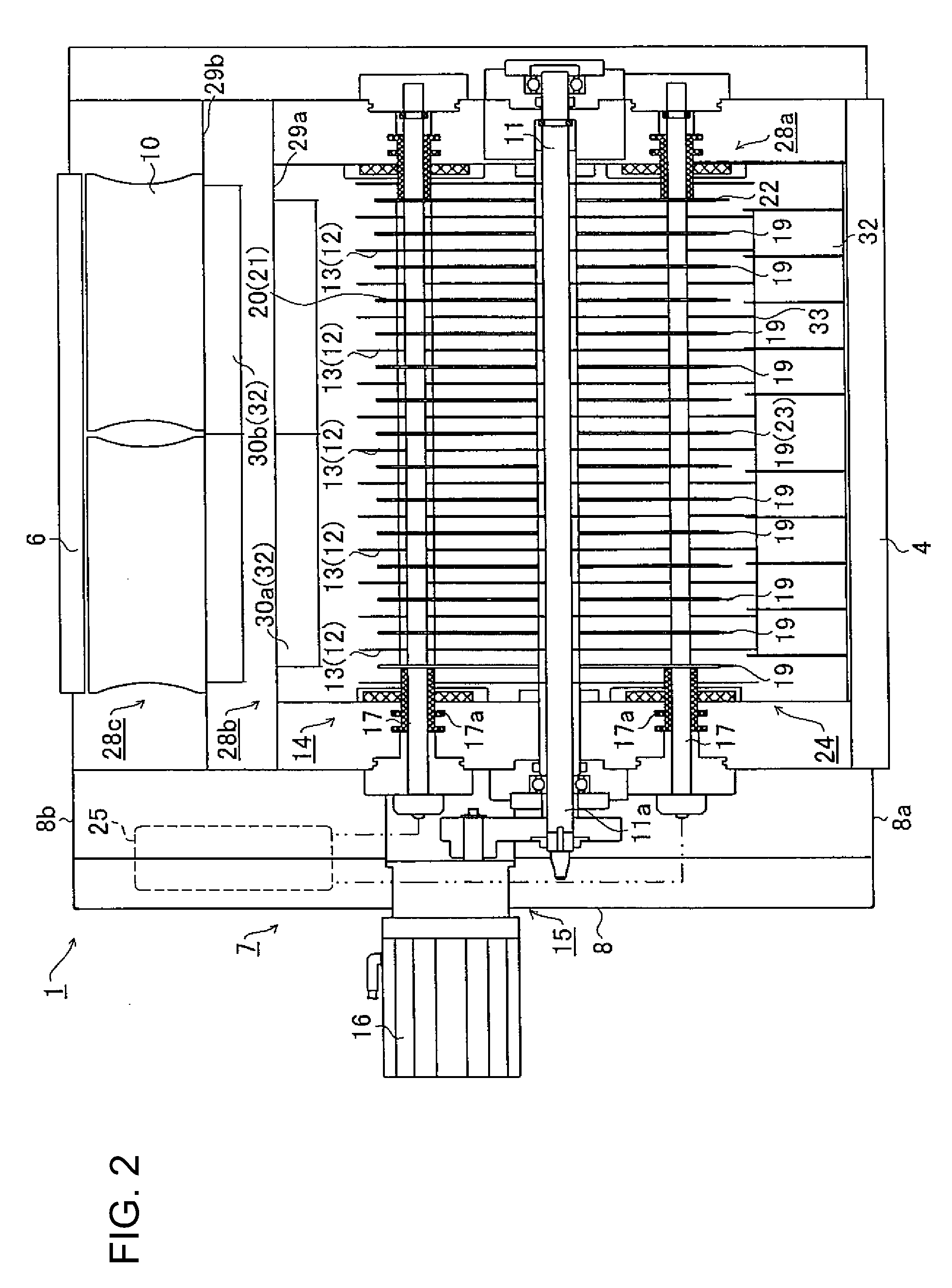
Coulomb force. Consequently, the particles that had been brought between the charging and absorption plates come under the repelling and absorptive effects, drawn to the absorption surface of the adsorption plate and collected. At this moment, the absorption plate is rotated by the plate rotating means that is connected to the adsorption shaft. Therefore, the positional relationship of the adsorption surface of the adsorption plate with the particles constantly changes, keeping the particles from accumulating in any specific site on the adsorption surface. In other words, the efficiency of adsorption and collection by the
Coulomb force is not reduced by accumulated particles and the dust-collecting
efficacy of the electrostatic precipitator is not compromised in a short period.
[0022]Thus, in the electrostatic precipitator of the present invention, the pointed ends of the discharge
electrode are arranged away from the plate edge of the adsorption plate and toward the side of the adsorption shaft. Specifically, contaminated air, which has passed through the inlet, reaches between a pair of opposing adsorption plates and arrives at the charging plate where the discharge
electrode is located. Because of the electrical field that has been formed by a supply of the discharge
voltage from the pointed ends of the discharge
electrode, a
corona discharge is generated toward the adsorption surface of the adsorption plate. Thus, the contaminated air that has passed between the adsorption plates is exposed to this
corona discharge. At this time, the pointed means is set back on the side of the adsorption shaft, the particles that have been charged by the
corona discharge are surrounded by the adsorption and charging plates. Consequently, the repulsive and adsorptive actions by the plates expedite
trapping of the fine particles.
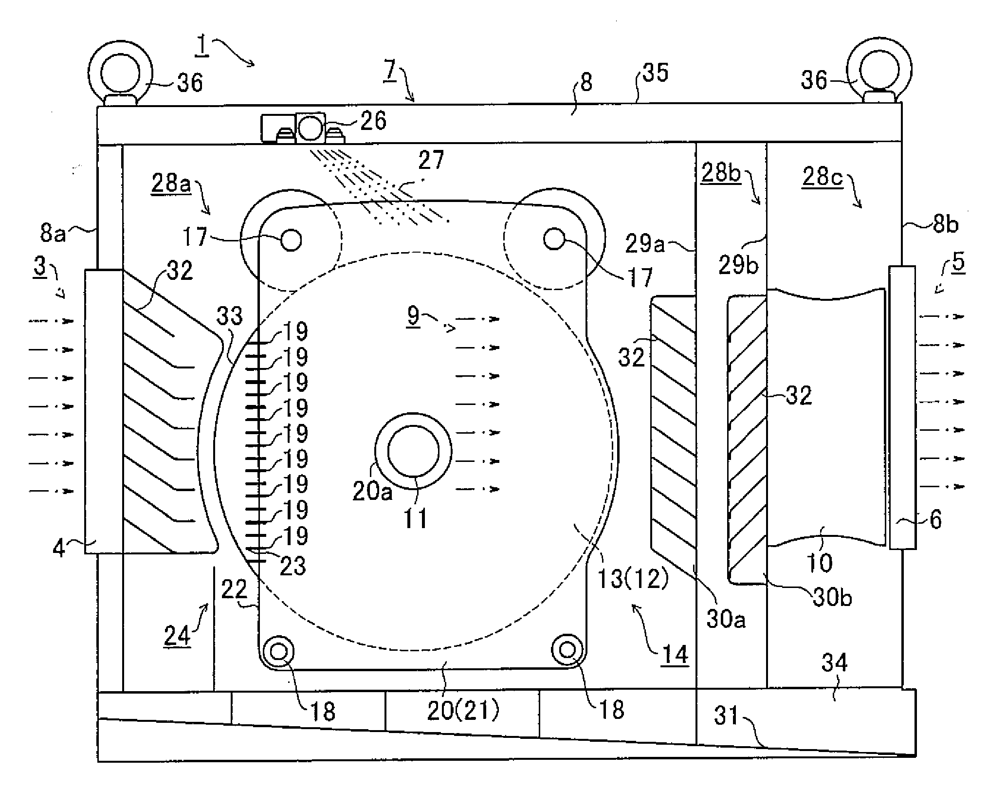
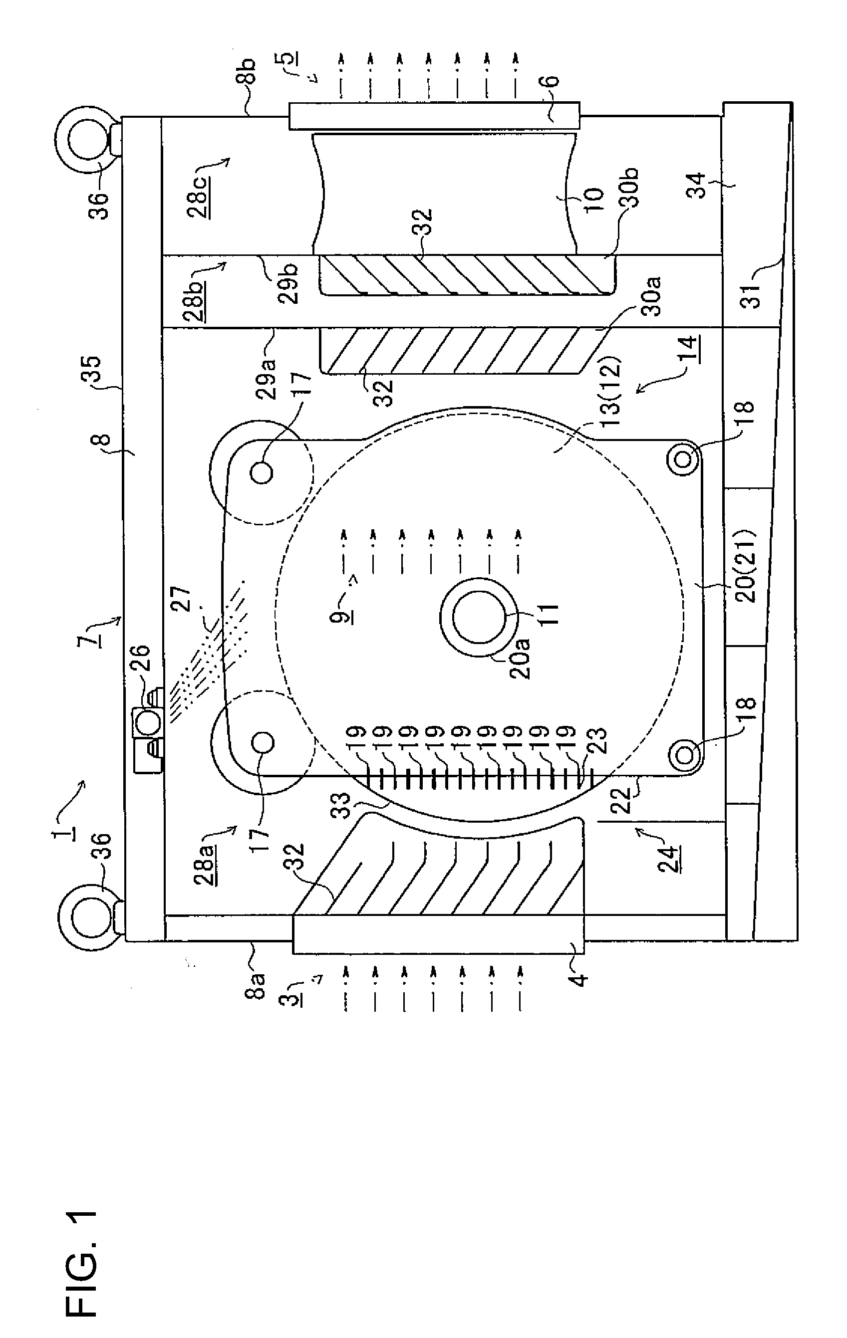
[0024]Thus, in the electrostatic precipitator of the present invention, the air duct inside the housing is divided into 3 sections. When contaminated air is to be purified by using this electrostatic precipitator, it is first introduced to the first section where the discharge and collecting means are located. In this first section, the fine particles are collected by means of the Coulomb force. Then, passing through the second and third sections, the cleansed air is released through the outlet. Specifically, to prevent the direct release, together with the clean air, of the fine particles that have been scattered and aggregated by the centrifugal action from the adsorption plates that rotate in the first section, the second section and the third sections that houses the
airflow generating means are created. Thus it became possible to improve the purity of the cleaned air that is released from the outlet.
[0026]Thus, in the electrostatic precipitator of the present invention, the pointed ends of the discharge electrode are arranged with an equal distance from the absorption surface of each opposing absorption plate. In this embodiment, the condition for generating a
corona discharge varies, depending on the distance from the pointed ends to absorption plates of different potentials. In other words, the smaller the distance between the pointed ends and the absorption plate, the more readily is the corona discharge generated. By equating the distance to the pointed ends of the discharge electrode means that is located between the absorption plates, the corona discharge is uniformly distributed on the absorption surface of both absorption plates. In an example for such a embodiment, a hole may be made where the discharge electrode may be inserted in the discharge plate and by inserting one end of the discharge electrode (corresponding to the side opposite the pointed end), the charge plate and the discharge electrode means may be built as a single unit, which makes it possible to maintain an equal distance from the absorption surface.
[0027]In the electrostatic precipitator of the present invention, for the means to charge fine particles with a corona discharge, discharge electrodes with pointed ends, which are arranged at the charge plate and opposing edges of the charge plate toward the intake, are used. Through this embodiment, the fine particles contained in contaminated air can be effectively charged. Because the charged particles can be collected by the rotating adsorption plates while the particle absorption surface undergoes relative changes, fine particles do not accumulate in any specific place on the absorption surface. Consequently, the likelihood of attenuating the Coulomb force and reducing the collection efficacy is unlikely. Furthermore, by adopting a embodiment in which only the adsorption plate is rotated, the structure of the electrostatic precipitator itself may be simplified and the maintenance (cleansing) operation of removing fine particles from the adsorptive surface can be conducted more simply than by the conventional method. In addition, the pointed ends of the discharge electrode are arranged equidistance from the pair of adsorption plates so that the corona discharge does not occur unevenly on one adsorption plate.

