System and Method to Compensate for Variable Fuel Injector Characterization in a Direct Injection System

Active Publication Date: 2009-03-05
FORD GLOBAL TECH LLC
View PDF4 Cites 7 Cited by
  • Summary
  • Abstract
  • Description
  • Claims
  • Application Information

AI Technical Summary

Benefits of technology

[0006]By recognizing transient conditions where needle bounce occurs and actively compensating for the transient conditions by modifying the opening delay time of the fuel injector needle based on fuel pressure and fuel injector needle bounce behavior, fuel injection timing accuracy may be maintained even as operating conditions change. In this way, fuel metering accuracy may be improved across the operating range of the engine system and cylinder balancing and fue

Problems solved by technology

Thus, if constant response time delays are utilized throughout varying operating conditions, fuel metering may become inaccurate.
In particular, the commanded fuel injection time may not match the desired fuel injection time due to variance of the actual response time delay compared with the constant response time delay value used by the fuel control system, which in turn, may result in an imbalance of delivered fuel and injection timing among each of the cylinders.
The cylinder imbalance may lead to torque variations among the cylinder which may result in increased noise, vibration, and harshness (NVH).
Further, the inaccurate fuel metering may lead to some, if not all, cylinders operating rich resulting in reduced fuel economy and increased tailpipe em

Method used


Image

  • System and Method to Compensate for Variable Fuel Injector Characterization in a Direct Injection System
  • System and Method to Compensate for Variable Fuel Injector Characterization in a Direct Injection System
  • System and Method to Compensate for Variable Fuel Injector Characterization in a Direct Injection System

Examples


Embodiment Construction

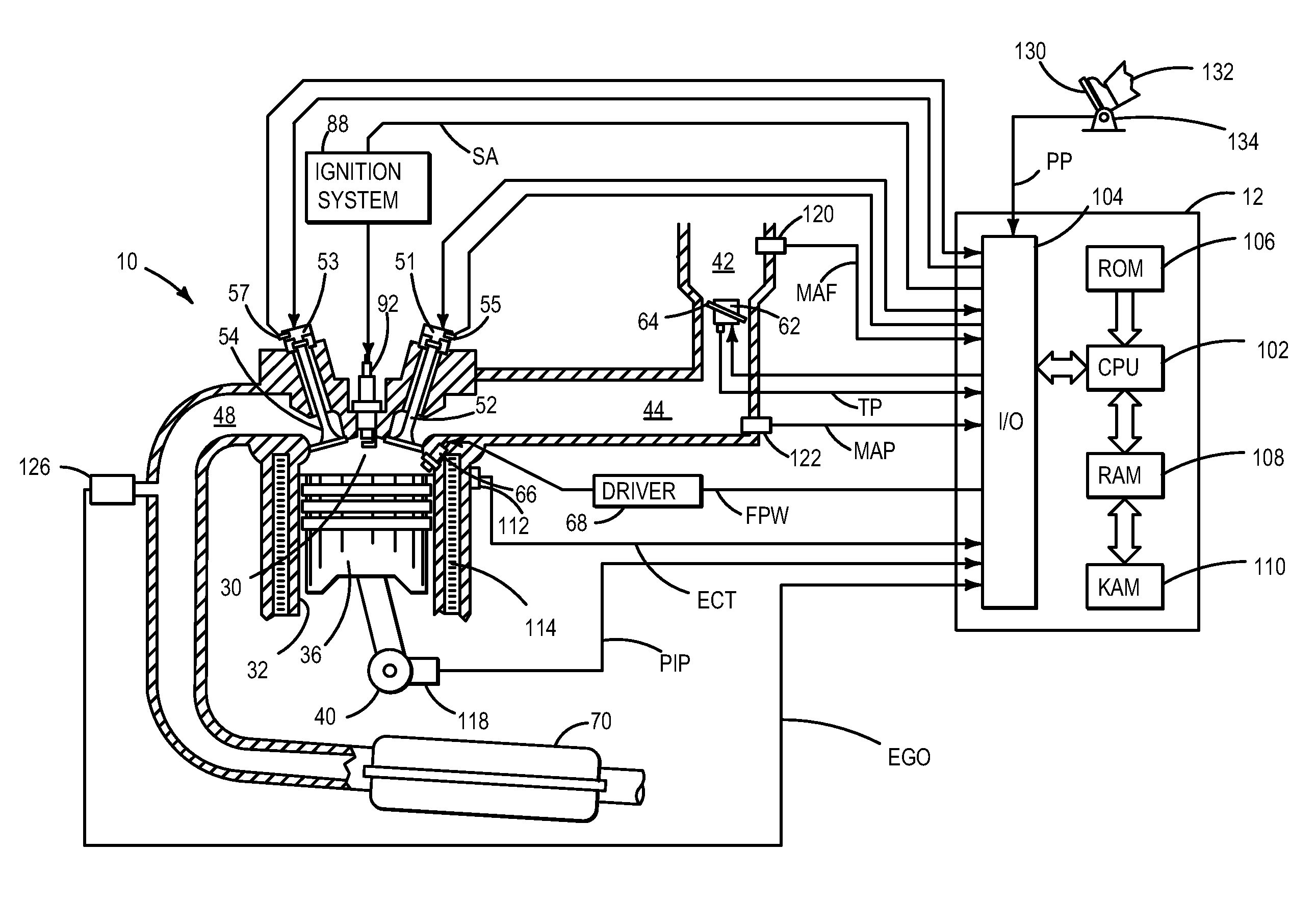
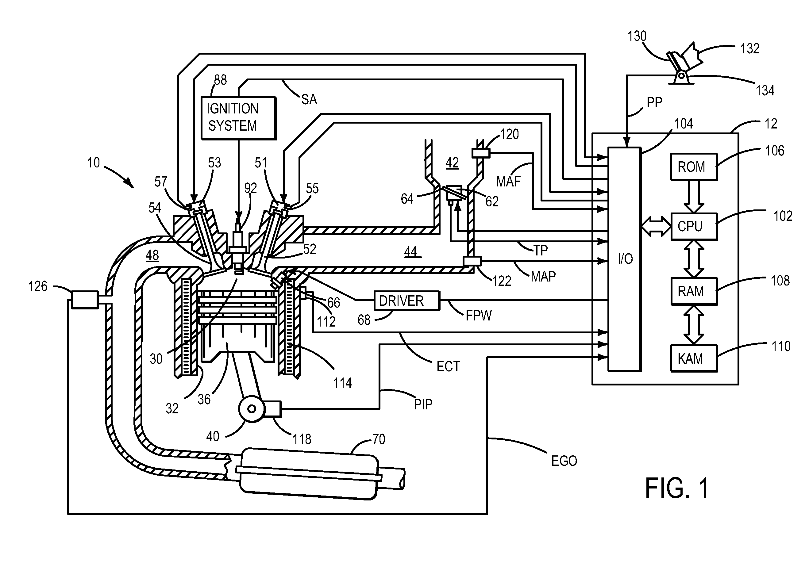
[0014]FIG. 1 is a schematic diagram showing one cylinder of multi-cylinder engine 10, which may be included in a propulsion system of an automobile. Engine 10 may be controlled at least partially by a control system including controller 12 and by input from a vehicle operator 132 via an input device 130. In this example, input device 130 includes an accelerator pedal and a pedal position sensor 134 for generating a proportional pedal position signal PP. Combustion chamber (i.e. cylinder) 30 of engine 10 may include combustion chamber walls 32 with piston 36 positioned therein. Piston 36 may be coupled to crankshaft 40 so that reciprocating motion of the piston is translated into rotational motion of the crankshaft. Crankshaft 40 may be coupled to at least one drive wheel of a vehicle via an intermediate transmission system. Further, a starter motor may be coupled to crankshaft 40 via a flywheel to enable a starting operation of engine 10.

[0015]Combustion chamber 30 may receive intak...


PUM


Abstract

A method for controlling fuel injection timing of at least one fuel injector in a direct injection fuel delivery system of an internal combustion engine during a mode of engine operation where a plurality of fuel injection events are performed by the at least one fuel injector during a cylinder event is provide. The method includes, during a first fuel injector needle bounce condition following the end of injection of a first fuel injection event, sending a start of injection signal for a second fuel injection event at a first time, and during a second fuel injector needle bounce condition following the end of injection of the first fuel injection that differs from the first fuel injector needle bounce condition, sending the start of injection signal for the second fuel injection event at a second time that is earlier than the first time.

Description

BACKGROUND AND SUMMARY[0001]In an engine system which utilizes a direct injection fuel delivery system, accurate fuel metering is imperative for efficient operation of the engine system. Fuel control strategies may take into account various delays relating to operation of fuel injectors in the direct injection fuel system in order to maintain accurate fuel control and, more particularly, accurate fuel injection timing. In particular, a control system may send fuel injection signals to one or more fuel injectors with timing that may be advanced in order to account for various types of delays associated with fuel injector hardware so that fuel injection may be performed at a desired time.[0002]For example, some fuel control strategies may advance signal timing to account for opening and closing delays of the fuel injectors. In one example, a fuel injection signal time may be advanced uniformly to account for either an opening delay or a closing delay of a fuel injector needle. In othe...

Claims


Application Information

Patent Timeline
IPC IPC(8): F02D41/30
CPCF02D41/402F02D2041/2055Y02T10/44F02D2250/16F02D2200/063Y02T10/40
Inventor THOMAS, JOSEPH LYLE
Owner FORD GLOBAL TECH LLC
Why Eureka
Try Eureka