
Lightning Protection System For A Wind Turbine Rotor Blade And A Method For Manufacturing Such A Blade

a protection system and wind turbine technology, applied in the field of wind turbine rotor blades, can solve the problems of severe damage to the rotor blade tip, increase the cost of operating the wind turbine, and reduce the operation tim

Active Publication Date: 2009-03-05
VESTAS WIND SYST AS
View PDF10 Cites 24 Cited by
  • Summary
  • Abstract
  • Description
  • Claims
  • Application Information

AI Technical Summary

Benefits of technology

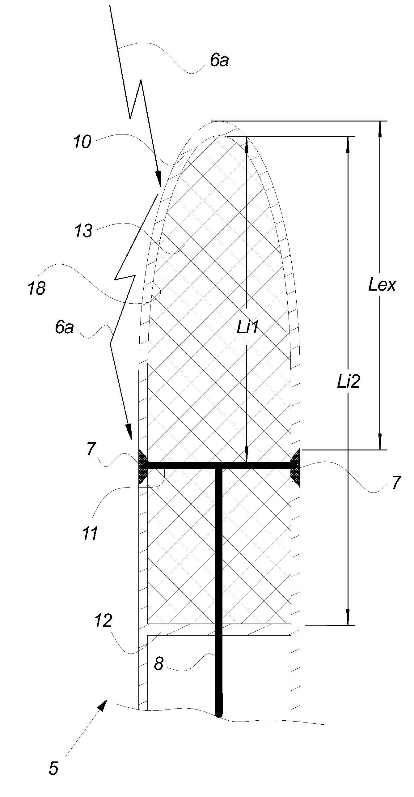
[0012]The invention provides a wind turbine rotor blade comprising means for changing at least one electric property of the rotor blade at the lightning receptor base, as compared to the electric properties of the ambient air by increasing the electric field supported between the lightning receptor base and the inner surface of the rotor blade.
[0013]Hereby is obtained an improved lightning protection system for a wind turbine blade by changing the internal electric property. The limit value, when dielectric breakdown inside the rotor blade occurs, is substantially increased, thereby preventing internal arching

Problems solved by technology

Lightning strikes against wind turbines has always been a problem needing attention because of damage to the wind turbine components reduces the operation time of the wind turbine and adds to the costs of operating the wind turbine.
However, the lightning does not always strike the lightning receptors when striking the wind turbine rotor blade.
The presence of the arc inside the rotor blade tip may cause severe damage to the rotor blade tip e.g. because of the significant increase in temperature in the confined space of the rotor blade tip.

Method used


Image

  • Lightning Protection System For A Wind Turbine Rotor Blade And A Method For Manufacturing Such A Blade
  • Lightning Protection System For A Wind Turbine Rotor Blade And A Method For Manufacturing Such A Blade
  • Lightning Protection System For A Wind Turbine Rotor Blade And A Method For Manufacturing Such A Blade

Examples


Embodiment Construction

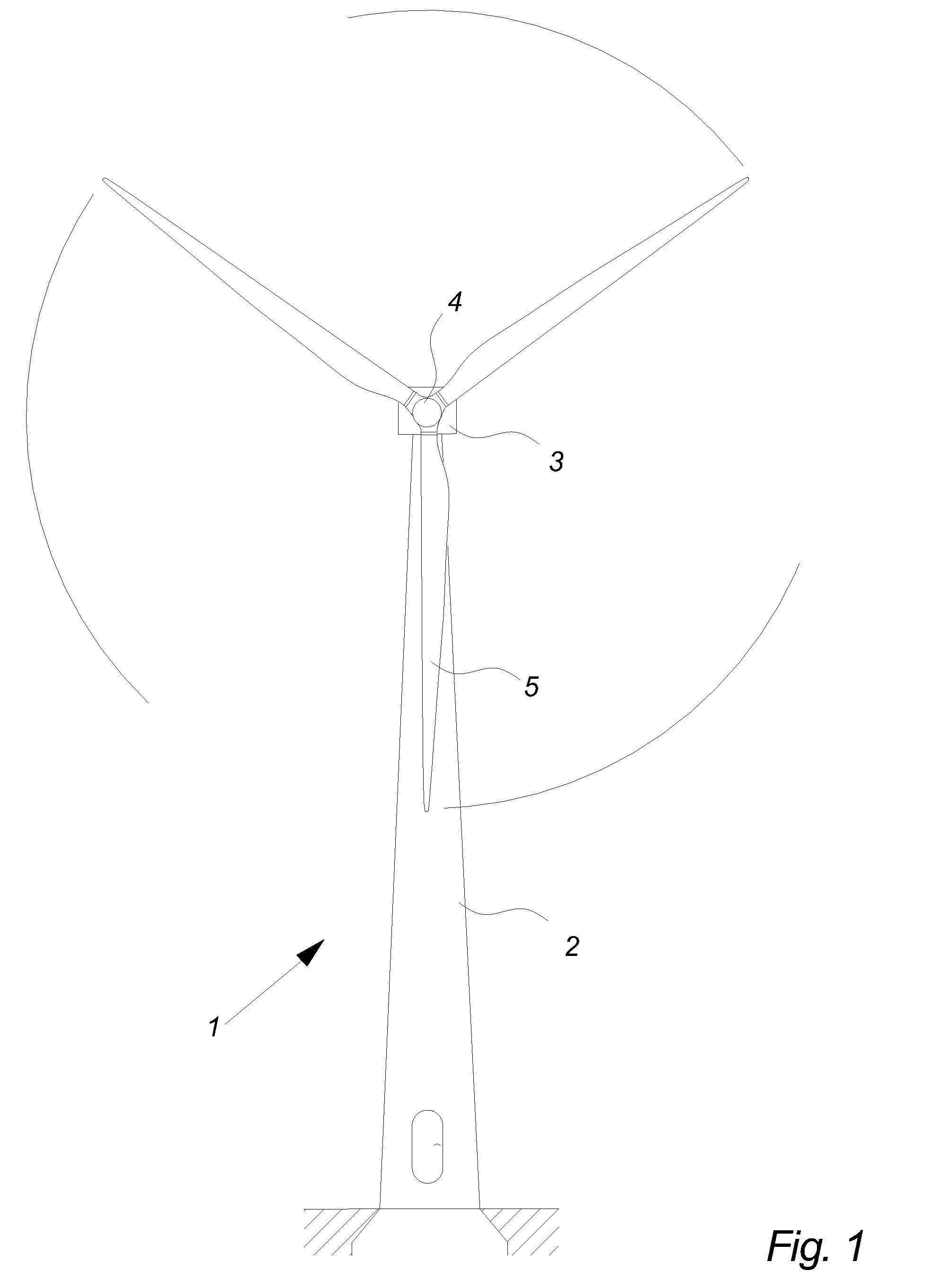
[0053]FIG. 1 illustrates a modern wind turbine 1. The wind turbine 1 comprises a tower 2 positioned on a foundation. A wind turbine nacelle 3 with a yaw mechanism is placed on top of the tower 2.

[0054]A low speed shaft extends out of the nacelle front and is connected with a wind turbine rotor through a wind turbine hub 4. The wind turbine rotor comprises at least one rotor blade e.g. three rotor blades 5 as illustrated. The rotor blades 5 may be pitchable in relation to the hub 4 by using pitch mechanisms or fixed mounted to the hub 4 as stall rotor blades.

[0055]The rotor blades 5 are hollow and thus having an outer surface and an inner surface.

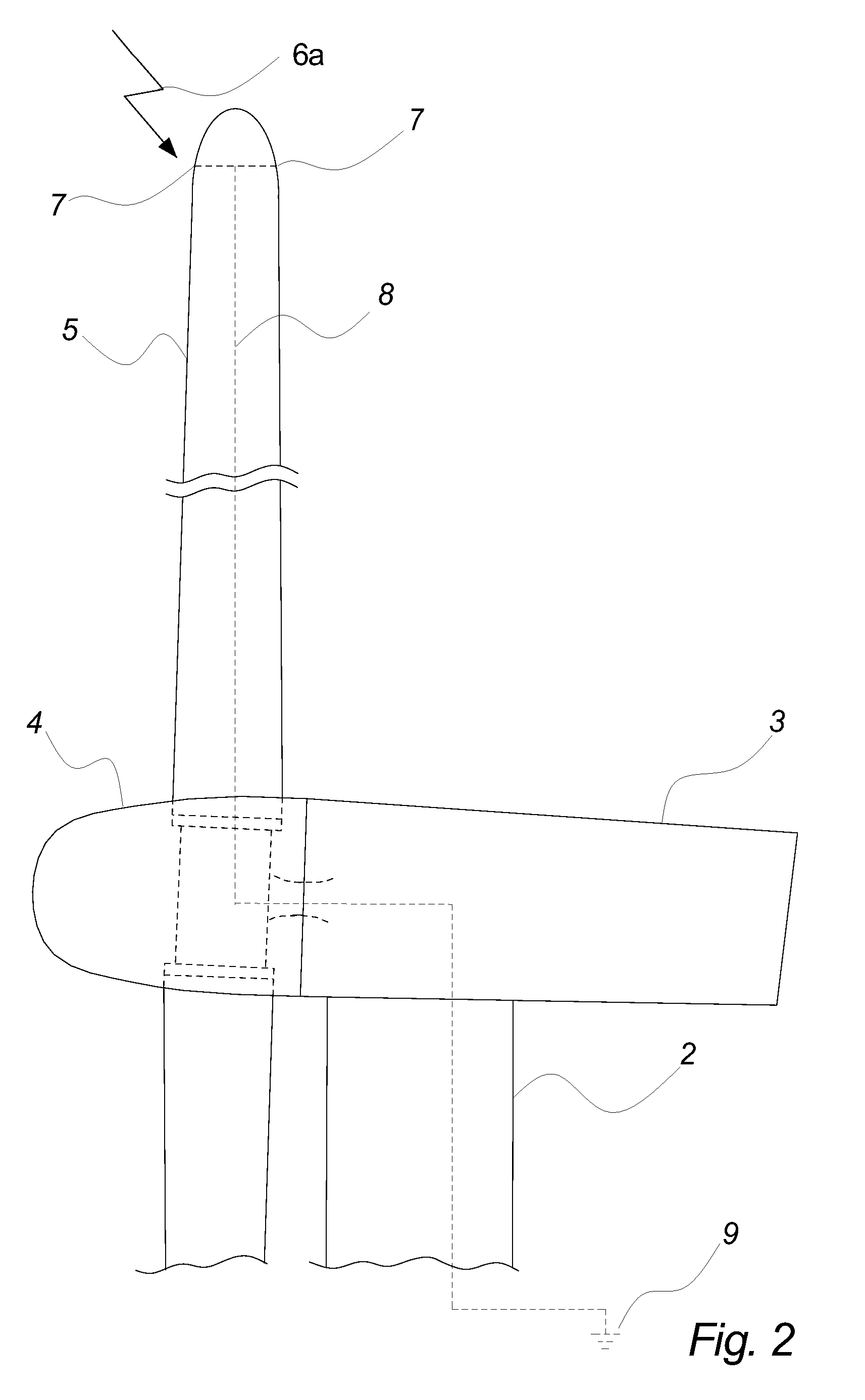
[0056]FIG. 2 illustrates a well known lightning protection system for a rotor blade 5 comprising one or more lightning receptors 7 made in a current conducting material. The receptors are arranged at the rotor blade outer surface and connected to a lightning down conductor 8 which provides a low impedance path to a ground connection 9.

[0057]...


PUM

PropertyMeasurementUnit
Lengthaaaaaaaaaa
Lengthaaaaaaaaaa
Fractionaaaaaaaaaa

Abstract

The invention relates to a wind turbine rotor blade comprising a blade tip and a lightning protection system. The rotor blade includes at least one lightning receptor at the surface of the blade in an external distance (Lex) from the distal end of the blade tip, and a lightning receptor base inside the rotor blade arranged at an first internal distance (Li1) from the distal end of the blade tip. The rotor blade further includes means for changing at least one electric property of the rotor blade at the lightning receptor base, as compared to the electric properties of the ambient air by increasing the electric field supported between the lightning receptor base and the inner surface of the rotor blade. The invention further relates to a method for manufacturing a wind turbine rotor blade.

Description

CROSS-REFERENCE TO RELATED APPLICATIONS[0001]The present application is a continuation of pending International patent application PCT / DK2007 / 000217 filed on May 8, 2007 which designates the United States and claims priority from Danish patent application PA 2006 00653 filed on May 9, 2006, the content of which is incorporated herein by reference.FIELD OF THE INVENTION[0002]The present invention relates to a wind turbine rotor blade, comprising a blade tip and a lightning protection system, said blade including at least one lightning receptor at the surface of the blade in an external distance from the distal end of the blade tip, and a lightning receptor base inside the rotor blade arranged at a first internal distance from the distal end of the blade tip, and a method for manufacturing a wind turbine rotor blade.BACKGROUND OF THE INVENTION[0003]Lightning strikes against wind turbines has always been a problem needing attention because of damage to the wind turbine components reduc...

Claims


Application Information

Patent Timeline
IPC IPC(8): H02G13/00F03D9/00B21D53/78H01R43/00
CPCF03D11/0033F05B2280/50F05B2280/6014F05C2251/00F05C2253/18H02G13/00Y10T29/49117H02G13/80Y10T29/49623Y10T29/49336Y10T29/49337Y10T29/49339Y10T29/49631Y02E10/722F03D80/30Y02E10/72Y02P70/50F05B2240/307
Inventor BERTELSEN, KIM
Owner VESTAS WIND SYST AS
Learn More