Method for forming head part of closed-type tube, method for manufacturing closed-type tube, and closed-type tubular container

a technology of closed-type tubes and head parts, which is applied in the direction of rigid containers, turning machine accessories, drawing profiling tools, etc., can solve the problems of difficult opening for use, the ability of these portions to protect contents, and the lower shape restoration capacity of aluminum tubes

Active Publication Date: 2009-03-05
KANSAI CHIYUUBU
View PDF7 Cites 2 Cited by
  • Summary
  • Abstract
  • Description
  • Claims
  • Application Information

AI Technical Summary

Benefits of technology

[0079]The effect attained by using the manufacturing method in accordance with the present invention is that a tubular container can be provided by a simple process in which, when a head part with a closing material attached thereto is formed at the tubular body part by using a compression method, an annular protrusion section can be formed at the outer peripheral section of the distal end surface of the convex section of the closing material by using stresses generated when a molten resin is pushed and filled under pressure, and this annular protrusion section can be enveloped with the molten resin, thereby forming a head part, and the closing material is prevented form falling into the container during opening.

Problems solved by technology

However, in the case of a laminated tube, for example, because the material of the head part molded by the compression method is a plasticizable plastic material and because the body part and the head part are not molded integrally, the ability to protect the contents causes concerns.
Thus, polyolefin resins, in particular polyethylene as a market base material, has been used as a material constituting the inner and outer layers of the body part of the laminated tube because of hot processability, chemical stability, flexibility, water resistance, utility, safety and sanitary properties, material cost thereof, etc., and polyethylene is most often used for the head part to provide for good bonding ability with the body part, and the ability of these portions to protect the contents is problematic.
Furthermore, a closing film is often formed to protect the contents, but if the head part is closed with polyethylene, then it is difficult to open for use and, therefore, it becomes necessary to close the opening of the head part with another member.
However, because aluminum tubes have lower shape restoration capacity than laminated tubes, the convenience of use thereof is degraded by deformation.
Furthermore, aluminum tubes are inferior to laminated tubes in terms of printing ability.
Because the closing material has to have a high strength to withstand processing such as deep drawing, a force necessary to pierce the closing material with the needle-shaped member is larger than the joining force between the closing material and head part and a problem is associated with the closing material falling into the tubular container.
Moreover, the distal end of the protruding section is weakened and sometimes even broken when the protruding section is mechanically molded.
Yet another problem is that when the head part is formed by a compression method, the protruding section formed outwardly from the outer peripheral surface of the convex section of the closing material becomes a hindrance and the molten resin cannot properly flow around to the distal end of the head part.

Method used


Image

  • Method for forming head part of closed-type tube, method for manufacturing closed-type tube, and closed-type tubular container
  • Method for forming head part of closed-type tube, method for manufacturing closed-type tube, and closed-type tubular container
  • Method for forming head part of closed-type tube, method for manufacturing closed-type tube, and closed-type tubular container

Examples


embodiment

[0098]A tubular body part for a body diameter (l6) size of 25 mm and an original sheet for a closing material were manufactured by the methods described in the aforementioned implementation mode.

[0099]Deep drawing was then conducted by using a punching machine. In the course of deep drawing, three types of closing materials were prepared: (i) a washer was not screwed on a holepin; (ii) one washer (thickness 0.4 mm) was screwed; (iii) two washers were screwed. A total of 18 closing materials (6 of each type) were manufactured.

[0100]The height of the convex section of the manufactured closing materials was measured and an average value was found. The respective values were as follows: (i) 12.88 mm, (ii) 12.44 mm, and (iii) 12.09 mm.

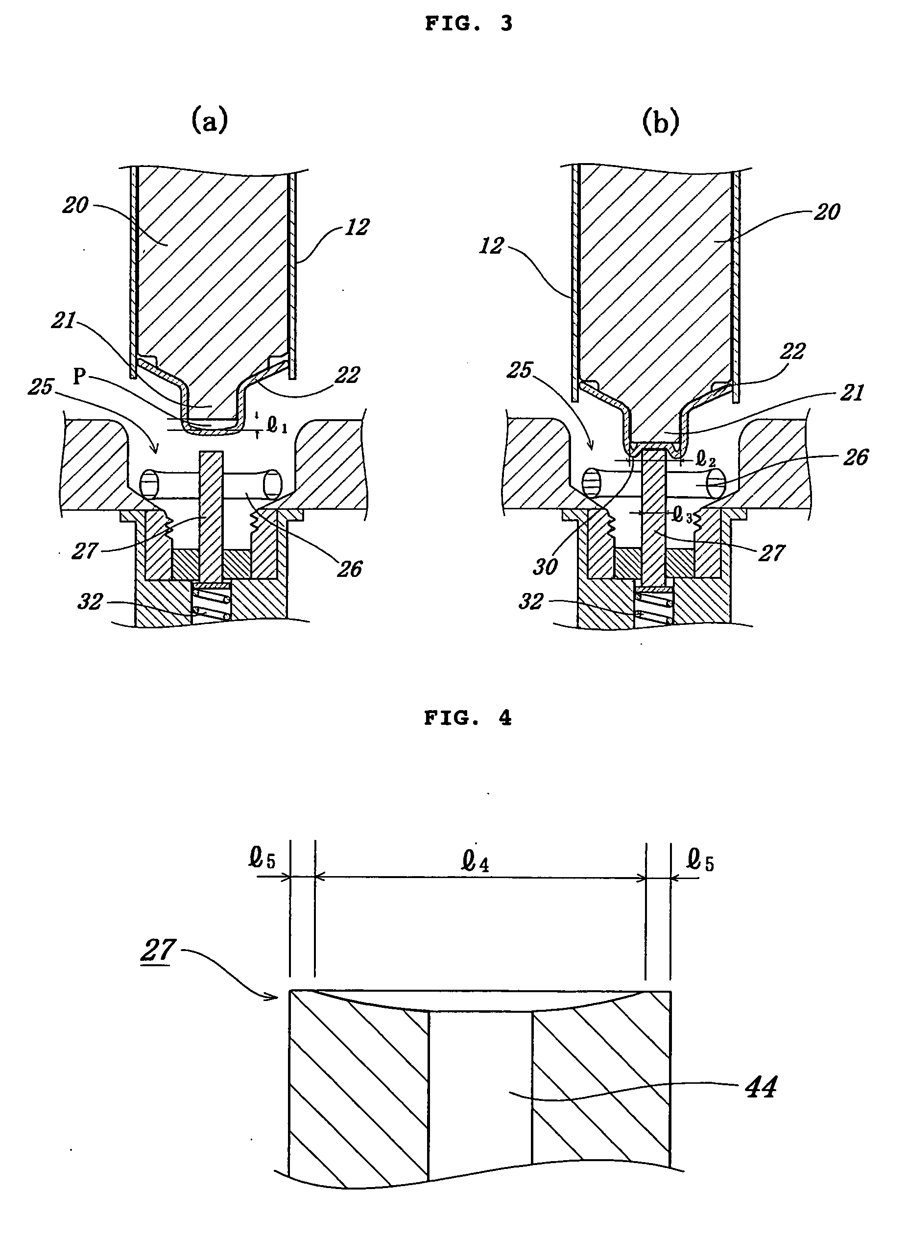
[0101]The tubular body part was then placed on the mandrel of the head-molding machine shown in FIG. 3(a), the above-described closing materials were successively fitted on the engagement section of the mandrel, and head parts were formed on the tubular bod...


PUM

PropertyMeasurementUnit
thicknessaaaaaaaaaa
diameteraaaaaaaaaa
diameteraaaaaaaaaa

Abstract

A cup-shaped closing material having a convex section is fitted on a protrusion-like engagement section of a distal end of a mandrel with a gap from the engagement section of the mandrel, a molten resin is then disposed in a cavity of a molding die and a holepin having an outer peripheral section of a distal end that is smaller than an outer periphery of the distal end surface of the convex section of the closing material is pressed against the distal end surface of the convex section of the closing material, whereby the distal end surface of the convex section of the closing material is pleated to form an annular protrusion section at the outer peripheral section, and the molten resin is caused to envelope the annular protrusion section, while being pushed and charged into the cavity, whereby the head part with the closing material attached thereto is formed.

Description

TECHNICAL FIELD[0001]The present invention relates to a method for forming a head part of a closed-type tube suitable for use in the manufacture of a tubular container of a type having a closed-type head part formed by using a compression method for increasing gas barrier properties of the head part in a tubular container used for containing food, seasonings, cosmetics, drugs, toothpaste, adhesives, creams, and the like, and also relates to a method for manufacturing a closed-type tube, and a closed-type tubular container.BACKGROUND ART[0002]Tubular containers having a closed-type head part designed to prevent the degradation, etc., of contents have been developed for containing food, medical products, industrial products, hair dyes, and the like.[0003]Such tubular containers are typically of the so-called aluminum tube type and a laminated tube type. With the former type, an aluminum slag is introduced into a cavity and pressure is applied to the aluminum slag by inserting a mandre...

Claims


Application Information

Patent Timeline
Patent Type & Authority Applications(United States)
IPC IPC(8): B65D8/04B65D85/00
CPCB29C43/18B29C43/36B29C2043/3665B65D2251/0093B65D35/12B65D51/223B65D2251/0015B29L2001/00
Inventor NISHIKAWA, KAZUO
Owner KANSAI CHIYUUBU
Why Eureka
Try Eureka