
Method of Detecting the Frequency of an Input Clock Signal of an Integrated Circuit and Integrated Circuit

a technology of integrated circuits and clock signals, applied in the field of methods of detecting the frequency of an input clock signal of an integrated circuit and to, can solve the problems of low flexibility or the need for additional processing

Inactive Publication Date: 2009-03-05
INFINEON TECH AG
View PDF7 Cites 20 Cited by
  • Summary
  • Abstract
  • Description
  • Claims
  • Application Information

AI Technical Summary

Benefits of technology

The present invention provides integrated circuits and methods that can detect the frequency of an input clock signal using a bridge circuit. This helps to improve the accuracy and reliability of the integrated circuit.

Problems solved by technology

However, this known approach has the problem of a low flexibility or of requiring additional processing so as to adopt the integrated circuit to the specific frequency of the input clock signal.

Method used


Image

  • Method of Detecting the Frequency of an Input Clock Signal of an Integrated Circuit and Integrated Circuit
  • Method of Detecting the Frequency of an Input Clock Signal of an Integrated Circuit and Integrated Circuit
  • Method of Detecting the Frequency of an Input Clock Signal of an Integrated Circuit and Integrated Circuit

Examples


Embodiment Construction

[0012]The following detailed description explains exemplary embodiments of the present invention. The description is not to be taken in a limiting sense, but is made only for the purpose of illustrating general principles of the invention. The scope of the invention, however, is only defined by the claims and is not intended to be limited by the exemplary embodiments described hereinafter.

[0013]It is to be understood that in the following detailed description any shown or described direct connection or coupling between two functional blocks, devices, components, or other physical or functional units could also be implemented by indirect connection or coupling.

[0014]In the following, embodiments of the invention will be described with reference to the accompanying drawings. The embodiments relate to an interface circuit and a method of determining the frequency of an input clock signal of the integrated circuit. The integrated circuit may be configured to perform specific functions i...


PUM


Abstract

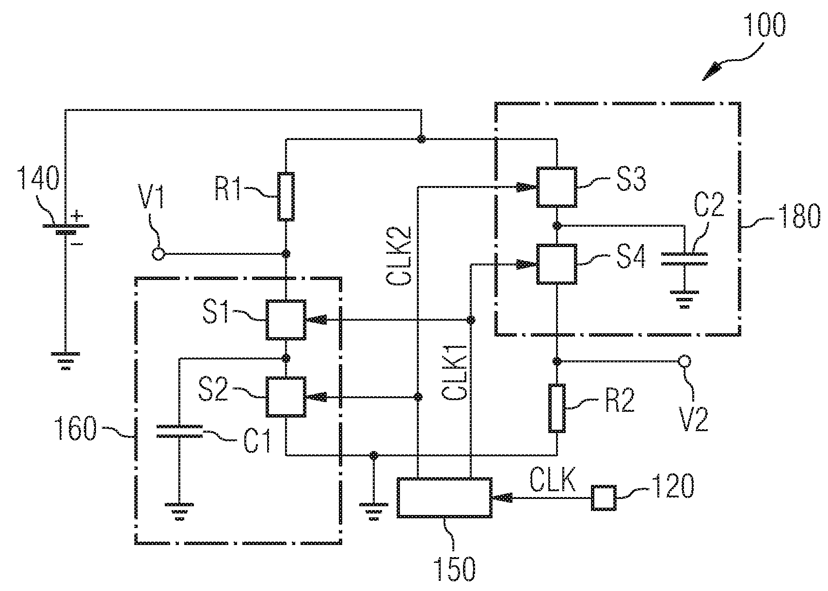
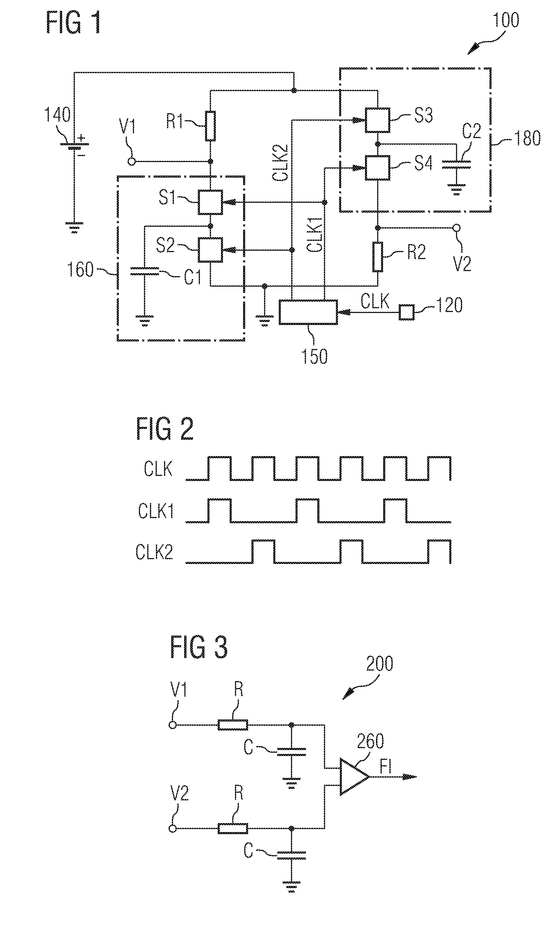
An integrated circuit includes a first switched capacitor element and a second switched capacitor element, which are coupled to form a bridge circuit, the first switched capacitor element being located in a first branch of the bridge circuit and the second switched capacitor element being located in a second branch of the bridge circuit. A detector circuit is coupled to the first branch and to the second branch of the bridge circuit. Switching signals of the first switched capacitor element and of the second switched capacitor element are generated on the basis of an input clock signal of the integrated circuit.

Description

TECHNICAL FIELD[0001]An embodiment of the present invention generally relates to a method of detecting the frequency of an input clock signal of an integrated circuit and to an integrated circuit configured to detect the frequency of its input clock signal.BACKGROUND[0002]In some types of integrated circuits, such as integrated circuits used in communication applications, there may be a need to discriminate between different frequencies of an input clock signal supplied to the integrated circuit. In this respect, it is known to use programming, e-fuses, clock specific programs or specific signals which are supplied from the outside to the integrated circuit to indicate which frequency of the input clock signal is used. For example, a signal supplied to a dedicated input pin of the integrated circuit may be used to indicate which one of a high frequency and a low frequency is used. The integrated circuit may use this information to adjust its internal operations. However, this known ...

Claims


Application Information

Patent Timeline
Patent Type & Authority Applications(United States)
IPC IPC(8): G01R23/02H03D13/00
CPCG01R23/15G01R23/09
Inventor HJELM, MIKAELHEDENAES, CHARLOTTAWIKLUND, BJOERN
Owner INFINEON TECH AG
Learn More