
Antenna structure and manufacture method thereof

a technology of antenna and antenna body, applied in the direction of antenna, antenna details, electrically short antennas, etc., can solve the problems of reducing performance, affecting the performance of antennas, so as to achieve the effect of concentrating the antenna field and increasing the performan

Inactive Publication Date: 2009-03-05
SERCOMM
View PDF5 Cites 11 Cited by
  • Summary
  • Abstract
  • Description
  • Claims
  • Application Information

AI Technical Summary

Benefits of technology

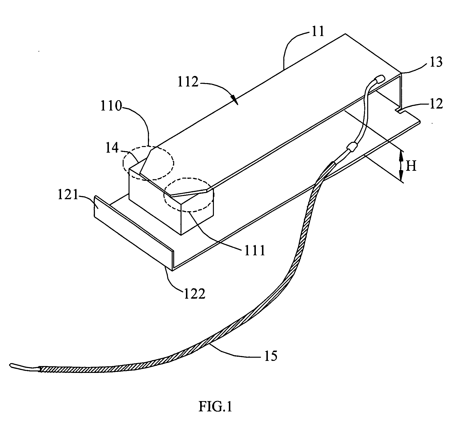
[0005]Briefly, it is a first object of the present invention to provide an antenna structure. The antenna structure is applied for an electronic device and wirelessly operated at least frequency band. The antenna structure is composed of a first antenna body, a second antenna body and a third body. The first antenna body is provided for generating radiations, and the second antenna body is connected to the first antenna body through the third body. The second antenna body has a folding portion upwardly extended from a tail portion of the second antenna body, and the folding portion is utilized to reflect scattered radiations generated by the first antenna body to increase broadband.
[0010]Since the folding portion is made, scattered radiations can be completely reflected to sufficiently utilize these radiations, thereby concentrating the antenna field and increasing performances.

Problems solved by technology

Most of radiations can be utilized and only few radiations may not be employed, resulting in wastage.
Consequently, the antenna field may not be concentrated and performance may be reduced.
Another drawback is that when the metal plate as a radiator transmits signals, the antenna gain is usually below 2.5 dBi (decibel), resulting in low efficiency.

Method used


Image

  • Antenna structure and manufacture method thereof
  • Antenna structure and manufacture method thereof
  • Antenna structure and manufacture method thereof

Examples


Embodiment Construction

[0017]Referring to the related figures for the antenna structure and its manufacture method according to a preferred embodiment of the present invention, wherein the same elements are described by the same reference numerals.

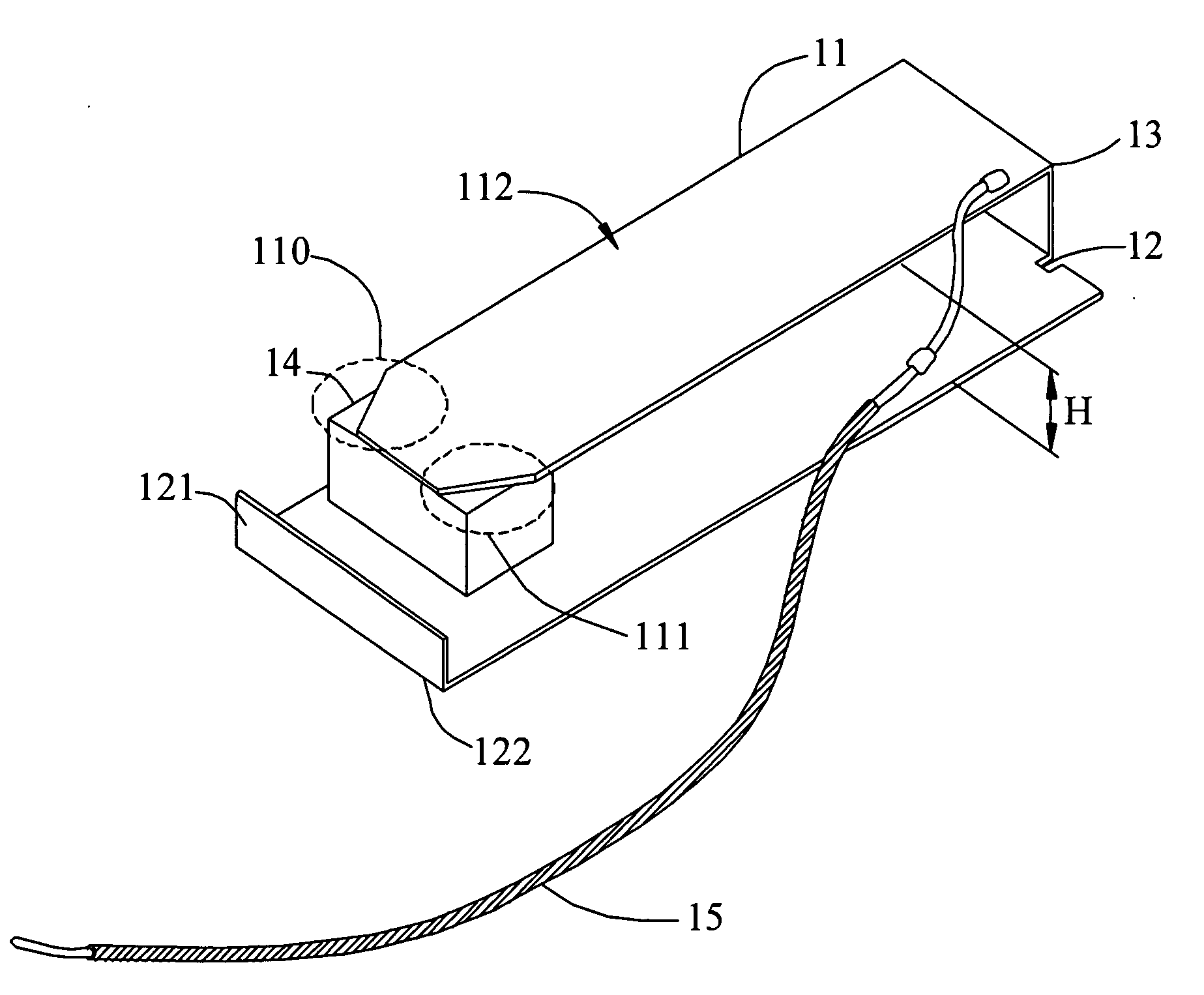
[0018]Referring to FIG. 1 for the schematic diagram illustrates an antenna structure according to an embodiment of the present invention. The antenna structure 10 is applied for an electronic device (not shown in the figure) and wirelessly operated at least a frequency band. The antenna structure 10 includes a first antenna body 11, a second antenna body 12 and a third body 13. The first antenna body 11 is provided for generating radiations. The second antenna body 12 is connected to the first antenna body 11 through the third body 13. It should be noted that the second antenna body 12 is parallel the first antenna body 11 to define a height H between the first antenna body 11 and the second antenna body 12. A folding portion 121 is upwardly extended from a tail...


PUM


Abstract

An antenna structure and its manufacture method are disclosed. The antenna structure is applied to an electronic device and wirelessly operated at least a frequency band. The antenna structure includes a first antenna body, a second antenna body connected to the first antenna body through a third body. The first antenna body is provided for generating radiations. The second antenna body is connected to the first antenna body through the third body. The second antenna body has a folding portion upwardly extended from a tail portion of the second antenna body to reflect scattered radiations generated by the first antenna body to increase broadband, and at least two beveled edges are formed at a side of the first antenna body to increase peak gain. The antenna structure is a PIFA antenna, and the folding portion is upwardly extended toward the first antenna body, thereby completely reflecting scattered radiations.

Description

FIELD OF THE INVENTION[0001]The present invention generally relates to an antenna structure and its manufacture method, and more specifically relates to utilize a folding portion disposed to a grounding plane of a PIFA (planar inverted-F antenna) to reflect scattered radiations, thereby increasing broadband and concentrating the antenna field.BACKGROUND OF THE INVENTION[0002]As wireless communication is in widespread use, antennas have become an important element for electronic devices such as computers, personal digital assistants, cell phones and other wireless network equipment to support wireless communication such as GSM (Global System for Mobile Communications, working frequency is between 890 MHz and 960 MHz frequency bands and impedance bandwidth is 7.6), WI-FI, WLAN (wireless local area network) or other wireless standards. Generally, the aforesaid antennas are disposed into the electronic devices, and so called embedded antennas. A planar inverted-F antenna (PIFA) is one o...

Claims


Application Information

Patent Timeline
Patent Type & Authority Applications(United States)
IPC IPC(8): H01Q1/24
CPCH01Q9/0421H01Q1/243
Inventor CHIANG, MENG-CHIEN
Owner SERCOMM
Learn More