Apparatus and method for a combined interferometric and image based geometric determination, particularly in the microsystem technology

a combined interferometric and image-based geometric determination technology, applied in the field of apparatus and a method for optical measurement, can solve the problems of troublesome interference effects in connection with interference microscopy due to additional image contrast caused by interference, and achieve the effect of small apparatus expenses and reduction of thermal disturbances

Active Publication Date: 2009-03-05
CARL MAHR HLDG
View PDF8 Cites 12 Cited by
  • Summary
  • Abstract
  • Description
  • Claims
  • Application Information

AI Technical Summary

Benefits of technology

[0022]The coupling of the measuring arrangement with mechanical positioning units for the X, Y and Z axes, which may be provided with suitable incremental measuring systems makes it possible to place measurements of different object areas in relation to one another. Depending on the measurement objective also rotational positioning axes may be expedient.
[0023]The apparatus according to the invention may be in the form of a compact sensor module and facilitates, with comparatively small apparatus expenses, a multitude of applications, specifically in the field of micro-system engineering. It accommodates the growing needs for measurement accuracy, measuring speed and process-related and flexible applicability. The use of LED's as light sources is advantageous over thermal radiators as they widely are used in the while light interferometry, with regard to design freedom, compactness, life and reduction of thermal disturbances.

Problems solved by technology

However, all microscopic procedures are, with regard to the achievable lateral resolution, subject to the limitations set by the diffraction-limited mapping.
If the evaluation of lateral structures based on the digitized light-microscopic imaging is to be performed with one of the above-mentioned interferometer arrangements, the interference effects necessarily occurring in connection with the interference microscopy because of the additional image contrasts caused thereby are troublesome.

Method used


Image

  • Apparatus and method for a combined interferometric and image based geometric determination, particularly in the microsystem technology
  • Apparatus and method for a combined interferometric and image based geometric determination, particularly in the microsystem technology
  • Apparatus and method for a combined interferometric and image based geometric determination, particularly in the microsystem technology

Examples


Embodiment Construction

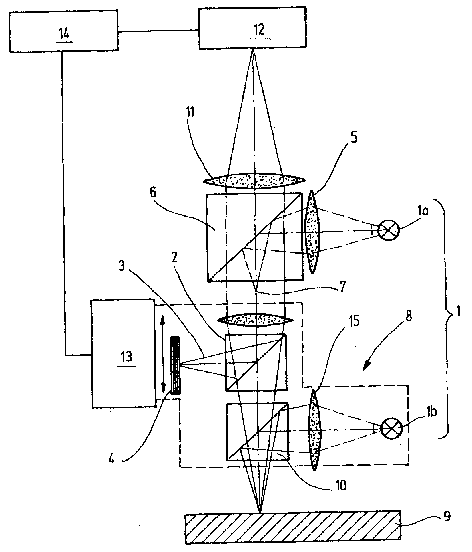
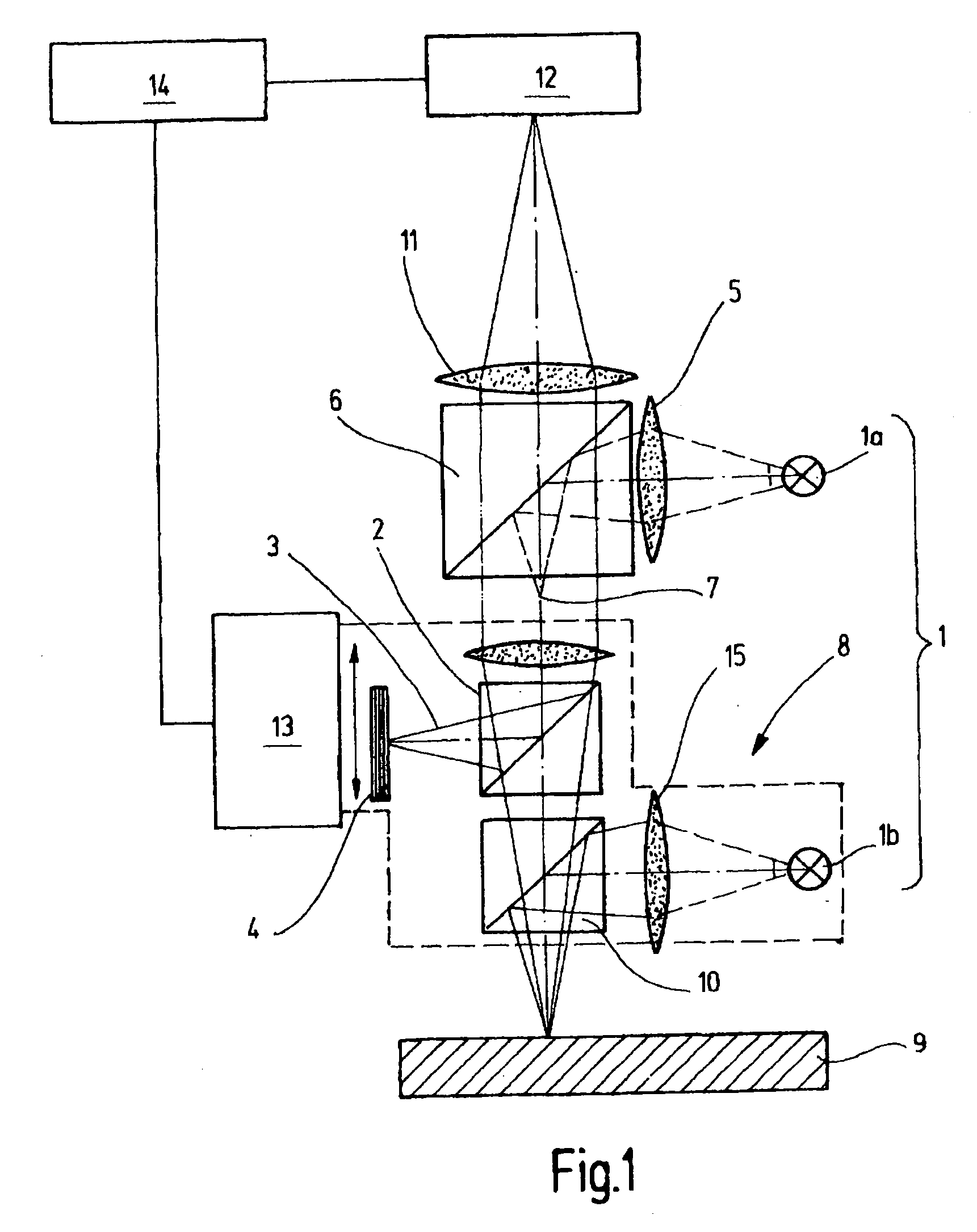
[0033]FIG. 1 shows an apparatus for a combined areal determination of height values of a measuring object 9 alternatively in an interferometric operating mode and in an image processing mode by means of optical imaging of the measuring object 9. Part of the apparatus is an illumination arrangement 1 with a first illumination device 1a and a second illumination device 1b for illuminating the measuring object 9. The illumination devices 1a, 1b comprise light sources for example with optical structure via which the light is directed in each case onto the surface of the measuring object 9.

[0034]The illumination devices 1a, 1b emit light of the same or different spectral compositions. For example, the first illuminating device 1a may be a white light LED which generates a relatively wide light spectrum. The second illumination device 1b is for example a blue light, that is, a short light wave, emitting diode. Alternatively both illumination devices 1a, 1b may be white light LED's or colo...


PUM


Abstract

The apparatus and method according to the invention includes an objective (8) which is capable of operating basically in two different measuring modes. In a first interference mode, a measuring object (9) is interference—optically measured. In a second imaging operating mode on a detector array (12) designed like a camera, an optical image is generated, which is supplied to an image processing routine. The switching over between the two operating modes occurs by switching the illumination devices which are associated with different locations of the beam path of the apparatus—when viewed from the camera, one in front of a beam divider and the other behind the beam divider, which couples a reference light path to the beam path.

Description

CROSS-REFERENCE TO RELATED APPLICATION[0001]This is a continuation-in-part application of pending international application PCT / EP 2007 / 003940 filed May 4, 2007 and claiming the priority of German application No. 10 2006 021 557.5 filed May 8, 2006.BACKGROUND OF THE INVENTION[0002]The invention concerns an apparatus and a method for an optical measurement of an object to be measured. The apparatus and the method are particularly suitable for measuring tasks in the microsystem technology.[0003]For measuring areas of height structures also on stepped objects optically with highest precision, the vertically scanning white-light interferometry (WLI) is particularly suitable. Common interferometric arrangements for this purpose are the Michelson interferometer, the Linnik-interferometer and the Mirau interferometer. In the WLI, a white light source, typically a halogen lamp is used for illumination. During the measurement the optical travel distance difference between the measuring beam ...

Claims


Application Information

Patent Timeline
Patent Type & Authority Applications(United States)
IPC IPC(8): G01B11/02
CPCG01B11/2441G01B9/04
Inventor STEFFENS, NORBERTLEHMANN, PETER
Owner CARL MAHR HLDG
Why Eureka
Try Eureka