
Sound processing apparatus, method for correcting phase difference, and computer readable storage medium

a phase difference and sound processing technology, applied in the field of sound processing apparatus, can solve the problems of increased cost of producing the sound processing apparatus, difficult application, individual differences of produced microphones, etc., and achieve the effect of correcting the change of characteristics and low production cos

Active Publication Date: 2009-03-05
FUJITSU LTD
View PDF7 Cites 8 Cited by
  • Summary
  • Abstract
  • Description
  • Claims
  • Application Information

AI Technical Summary

Benefits of technology

[0009]Therefore, an object of the present invention is to provide an apparatuses capable of correcting the variation of sensitivity of a plurality of microphone included in the apparatus with low production cost and of correcting the change of characteristics caused by deterioration with age.

Problems solved by technology

However, typically produced microphones have individual differences such as sensitivity differences within predetermined specifications.
Therefore the cost for producing the sound processing apparatus increases.
Besides, after shipment, the proposed methods would be difficult to be applied against characteristic alteration, such as deterioration with age, the characteristic of the microphones will differ from each other.

Method used

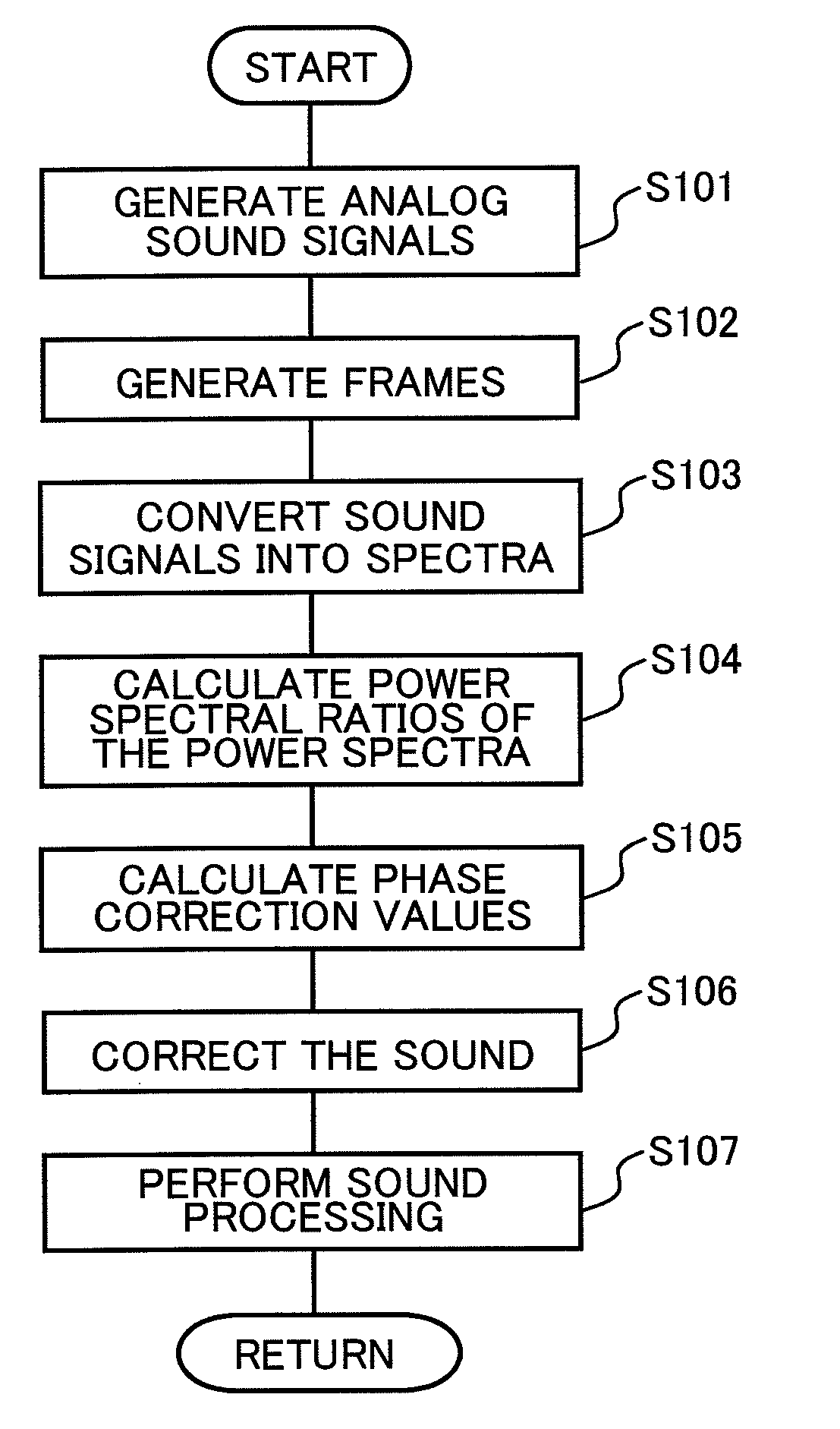

Image

  • Sound processing apparatus, method for correcting phase difference, and computer readable storage medium
  • Sound processing apparatus, method for correcting phase difference, and computer readable storage medium
  • Sound processing apparatus, method for correcting phase difference, and computer readable storage medium

Examples


first embodiment

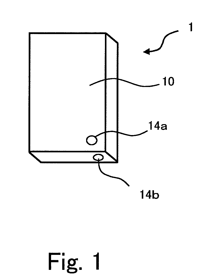
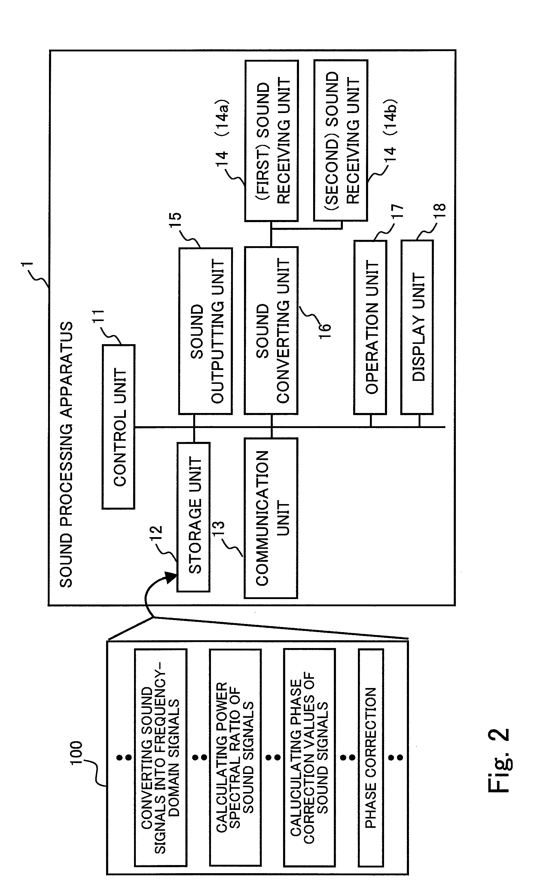
[0024]FIG. 1 shows a perspective view illustrating an example of an outside shape of a sound processing apparatus 1 according to the first embodiment of the present invention. In FIG. 1, reference number 1 denotes the sound processing apparatus 1 having a rectangular-parallelepiped casing 10 and of the present invention uses a computer such as used in a cellular phone which is also set in the casing 10. The sound processing apparatus 1 is included a rectangular-parallelepiped casing 10. The first sound receiving unit 14a using a microphone such as a condenser microphone for receiving sound produced by a speaker is disposed at the front of the casing 10. Moreover, the second sound receiving unit 14b such as a condenser microphone is disposed at the bottom of the casing 10. The second sound receiving unit 14b is preferably a same kind of microphone used as the first sound receiving unit 14a. Sounds come from various directions to the sound processing apparatus 1, and the sound process...

second embodiment

[0049]In a second embodiment, the sound processing apparatus according to the first embodiment is modified in view of, for example, reducing the processing load and preventing sudden changes in sound quality. Since the outside shape and exemplary configurations of hardware of the sound processing apparatus according to the second embodiment are similar to those according to the first embodiment, those according to first embodiment will be referred and the descriptions thereof will be omitted. In the description below, the same reference numbers are used for components substantially the same as those in the first embodiment.

[0050]FIG. 9 is a functional block diagram illustrating an exemplary function of a sound processing apparatus 1 according to the second embodiment. The sound processing apparatus 1 of the present invention includes a first sound receiving unit 14a and a second sound receiving unit 14b, an anti-aliasing filter 160, and A / D converter 161 that performs analog-to-digi...


PUM


Abstract

There is provided a sound processing apparatus for processing received sounds. A plurality of sound receiving units which are included in the apparatus output individually a sound signal corresponding to a received sound, then the sound signals in a time domain are converted into respective converted signal in a frequency domain, and a spectral ratio between the two converted signals is calculated for driving a phase correction value which corrects a phase of the sound signal.

Description

BACKGROUND OF THE INVENTION[0001]1. Field of the Invention[0002]The present invention relates to a sound processing apparatus for converting sounds receiving by a plurality of sound receiving units to sound signals which are processed. More specifically, the present invention relates to a sound processing apparatus for correcting the phase differences between the sound signals, method, and a computer readable storage medium a storing a computer program therefor.[0003]2. Description of the Related Art[0004]Various sound processing apparatuses for, for example, identification of directions from which sound comes using a plurality of microphones have been developed and are in practical use. One of these apparatus will now be described. FIG. 11 is a perspective view illustrating an example of an outside shape of the sound processing apparatus. In FIG. 11, a shape of a housing of a cellular phone in which the sound processing apparatus 1000 is built is as a rectangular parallelepiped, th...

Claims


Application Information

Patent Timeline
IPC IPC(8): H04R1/40G10L21/0208G10L21/0232
CPCH04R3/005H04R2201/403H04R29/006H04R25/407
Inventor HAYAKAWA, SHOJI
Owner FUJITSU LTD
Learn More