Exposure method and apparatus, maintenance method, and device manufacturing method

Inactive Publication Date: 2009-03-05
NIKON CORP
View PDF59 Cites 41 Cited by
  • Summary
  • Abstract
  • Description
  • Claims
  • Application Information

AI Technical Summary

Benefits of technology

[0020]According to the sixth aspect of the present invention, it is possible to easily judge whether or not the state of the substrate as the exposure obje

Problems solved by technology

However, it is feared that any minute foreign matter (particles) including the resist residue, etc. might adhere during the exposure based on the liquid immersion method to a portion which comes into contact with the liquid, for example, a portion which comes into contact with the liquid including the flow passages for the liquid of the liquid supply mechanism and the liquid recovery mechanism, etc.
There is such a possibility that the foreign matter, which adheres as described above, enters into and mixed with the liquid again and adheres to the surface of the substrate as the exposure objective during the exposure to be performed thereafter, and the foreign matter may become any factor of the defect such as the shape deficiency or unsatisfactory shape of the pattern to be transferred.
However, it is feared for some of such materials that any shape error or the like may be caused at the stage of the resist pattern in the case of the exposure based on the liquid immer

Method used


Image

  • Exposure method and apparatus, maintenance method, and device manufacturing method
  • Exposure method and apparatus, maintenance method, and device manufacturing method
  • Exposure method and apparatus, maintenance method, and device manufacturing method

Examples


first embodiment

[0041]A preferred example of the first embodiment of the present invention will be explained below with reference to the drawings.

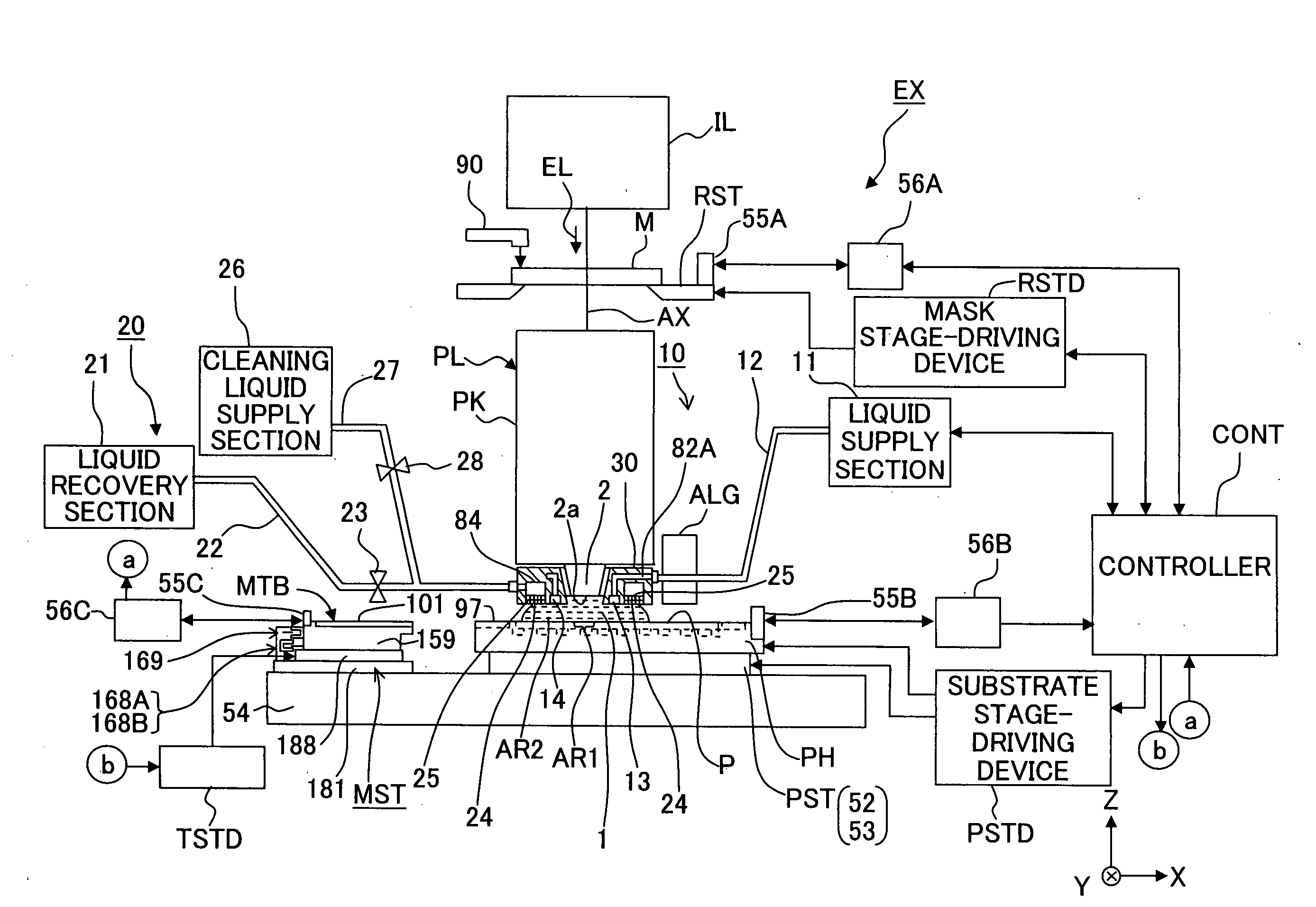
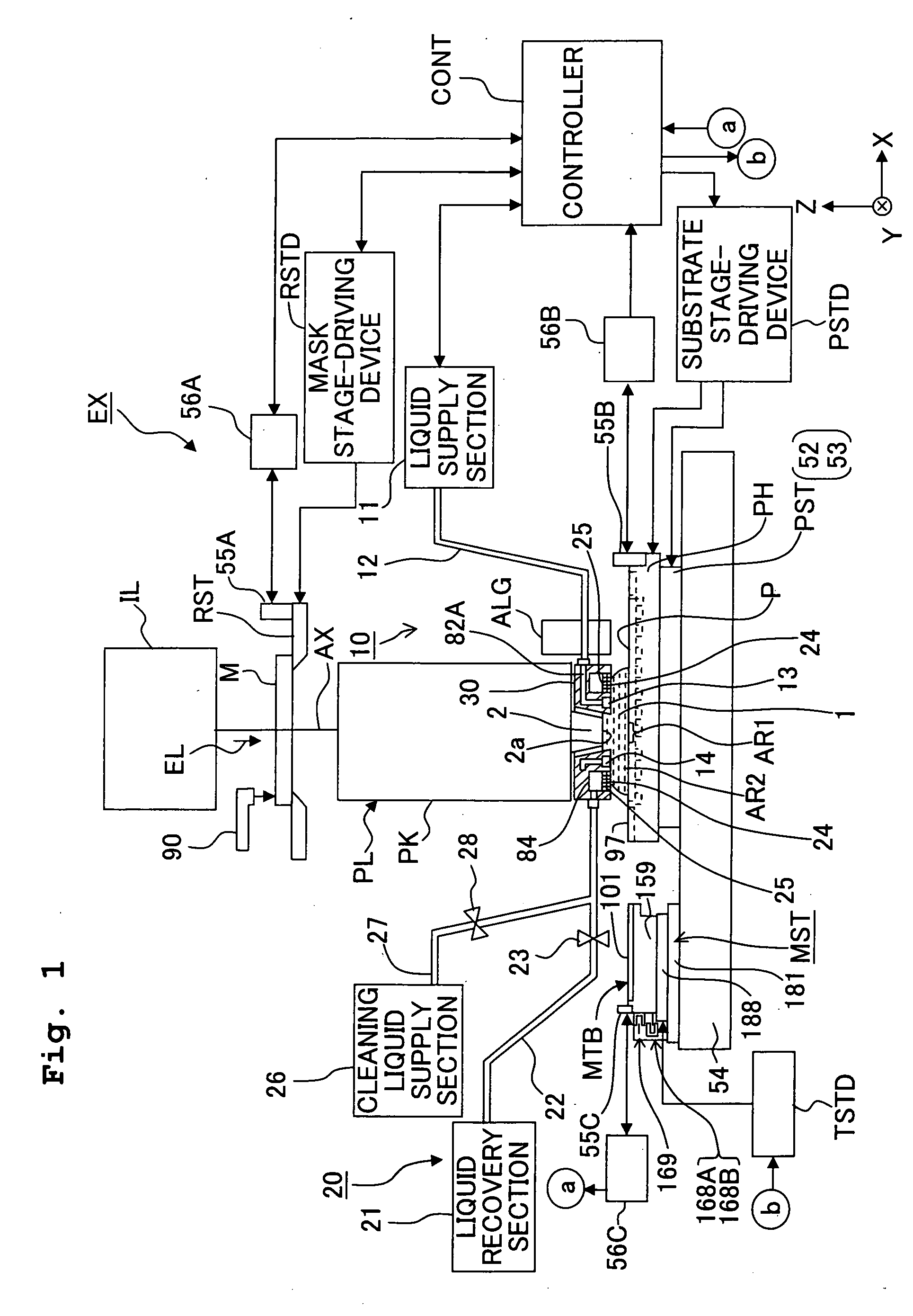
[0042]FIG. 1 shows a schematic construction of an exposure apparatus EX constructed of a scanning type exposure apparatus (so-called scanning stepper) according to this embodiment. With reference to FIG. 1, the exposure apparatus EX includes a mask stage RST which supports a mask M having a transferring pattern (pattern to be transferred) formed in the mask M; a substrate stage PST which supports a substrate P as an exposure objective; an illumination optical system IL which illuminates, with an exposure light EL, the mask M supported by the mask stage RST; a projection optical system PL which projects an image of the pattern (pattern image) of the mask M, illuminated with the exposure light EL, onto a projection area AR1 on the substrate P supported by the substrate stage PST; a measuring stage MST which has a reference mark for the alignment formed in t...

second embodiment

[0131]An exposure apparatus EX′ and an exposure method according to the second embodiment of the present invention will be explained with reference to FIGS. 9 to 15. In the following description, the constitutive parts or components, which are same as or equivalent to those of the first embodiment, are designated by the same reference numerals, any explanation of which will be simplified or omitted.

[0132]FIG. 9 is a schematic construction view of the scanning type exposure apparatus EX′ of this embodiment. With reference to FIG. 9, the exposure apparatus EX′ includes a mask stage RST which supports a mask M; a substrate stage PST which supports a substrate P; an illumination optical system IL which illuminates, with an exposure light EL, the mask M supported by the mask stage RST; a projection optical system PL which projects an image of a pattern (pattern image) of the mask M illuminated with the exposure light EL onto the substrate P supported by the substrate stage PST; a control...


PUM


Abstract

An exposure method for exposing a substrate with an exposure light via an projection optical system and a liquid includes: a first step of optically observing a liquid contact portion which comes into contact with the liquid and storing first image data obtained by the optical observation; a second step of optically observing the liquid contact portion after the liquid contact portion came into contact with the liquid, for example, after the liquid immersion exposure and obtaining second image data obtained by the optical observation; and a third step of comparing the first image data and the second image data to judge whether abnormality of observation objective portion is present or absent. It is possible to efficiently judge whether or not the abnormality of the liquid-contact portion, of the exposure apparatus which performs the exposure by the immersion method, is present or absent.

Description

CROSS-REFERENCE[0001]This application is a Continuation Application of International Application No. PCT / JP2007 / 060411 which was filed on May 22, 2007 claiming the conventional priority of Japanese patent Applications No. 2006-141024 filed on May 22, 2006 and No. 2006-143452 filed on May 23, 2006.BACKGROUND OF THE INVENTION[0002]1. Field of the Invention[0003]The present invention relates to an exposure technique for exposing a substrate with an exposure light through a liquid, a maintenance technique for an exposure apparatus using the exposure technique, and a technique for producing a device using the exposure technique.[0004]2. Description of the Related Art[0005]A microdevice (electronic device), which includes a semiconductor device, a liquid crystal display device, etc. is produced by the so-called photolithography technique wherein a pattern, which is formed on a mask such as a reticle, is transferred onto a substrate such as a wafer which is coated with a photosensitive mat...

Claims


Application Information

Patent Timeline
IPC IPC(8): G03F7/20G01T1/16G03B27/42
CPCG03F7/70341G03F7/7085G03F9/7096G03F7/70925G03F9/7088G03F7/70916G03F7/7065
Inventor NAKANO, KATSUSHI
Owner NIKON CORP
Why Eureka
Try Eureka