Backing material, ultrasonic probe, ultrasonic endoscope, ultrasonic diagnostic apparatus, and ultrasonic endoscopic apparatus

Inactive Publication Date: 2009-03-05
FUJIFILM CORP
View PDF5 Cites 98 Cited by
  • Summary
  • Abstract
  • Description
  • Claims
  • Application Information

AI Technical Summary

Benefits of technology

[0023]According to the present invention, since the heat conducting fibers having the larger coefficient of thermal conductivity than that of the backing base material, and penetrating the backing base material without disconnection from the first face of the backing material in contact with the at least one vibrator to the second face different from the first face of th

Problems solved by technology

However, not the whole energy of the drive signals is converted into acoustic energy but the considerable amount of energy turns into heat, and the surface temperature of the ultrasonic probe rises due to the heat generated from the ultrasonic transducers.
Because of the generated heat, problems of breakage of the ultrasonic vibrator surface and the acoustic matching layer, deterioration in acoustic characteristics due to separation or the like, degradation in reliability and quality are caused.
Further, because of the surface temperature rise of the ultrasonic probe, a problem of low-temperature burn or the like that reduces safety is caused.
Further, with microfabrication of vibrators, increase in the number of vibrators, higher density of vibrators, two-dimensional arrangement of vibrator array, and stacking of vibrator array, the problem of heat generation and surface temperature rise of the ultrasonic probe becomes more serious and it becomes difficult to draw lead wires out from the ultrasonic probe.
Accordingly, problems of reduction in reliability, reduction in mass productivity, lower yield, and higher cost are caused.
However, according to Document 1, since the heat generated in the piezoelectric elements transfers to the support material via the acoustic absorbing layer, the heat radiation efficiency is not so much improved unless the coefficient of thermal conductivity of the acoustic absorbing l

Method used


Image

  • Backing material, ultrasonic probe, ultrasonic endoscope, ultrasonic diagnostic apparatus, and ultrasonic endoscopic apparatus
  • Backing material, ultrasonic probe, ultrasonic endoscope, ultrasonic diagnostic apparatus, and ultrasonic endoscopic apparatus
  • Backing material, ultrasonic probe, ultrasonic endoscope, ultrasonic diagnostic apparatus, and ultrasonic endoscopic apparatus

Examples


first embodiment

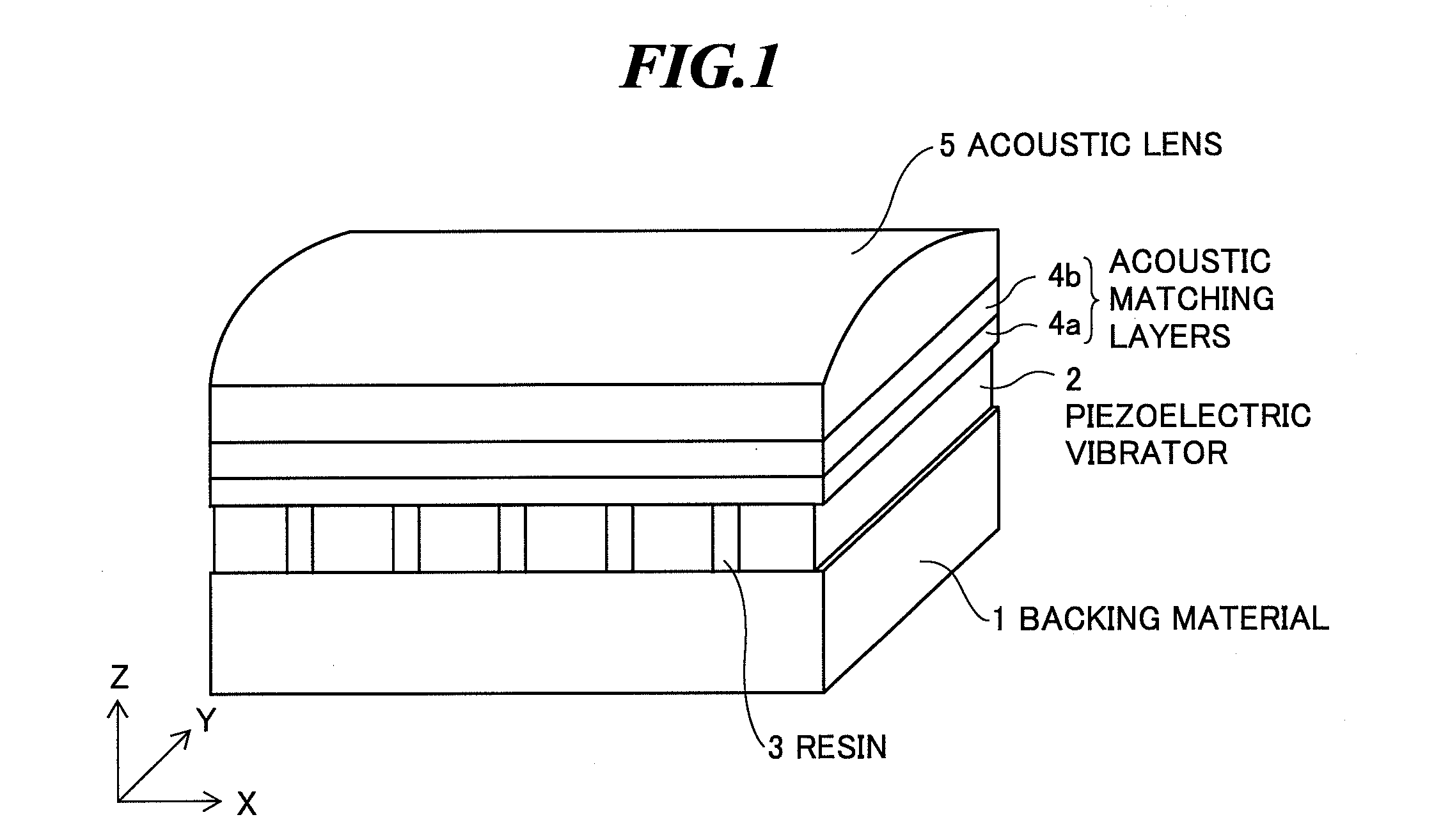
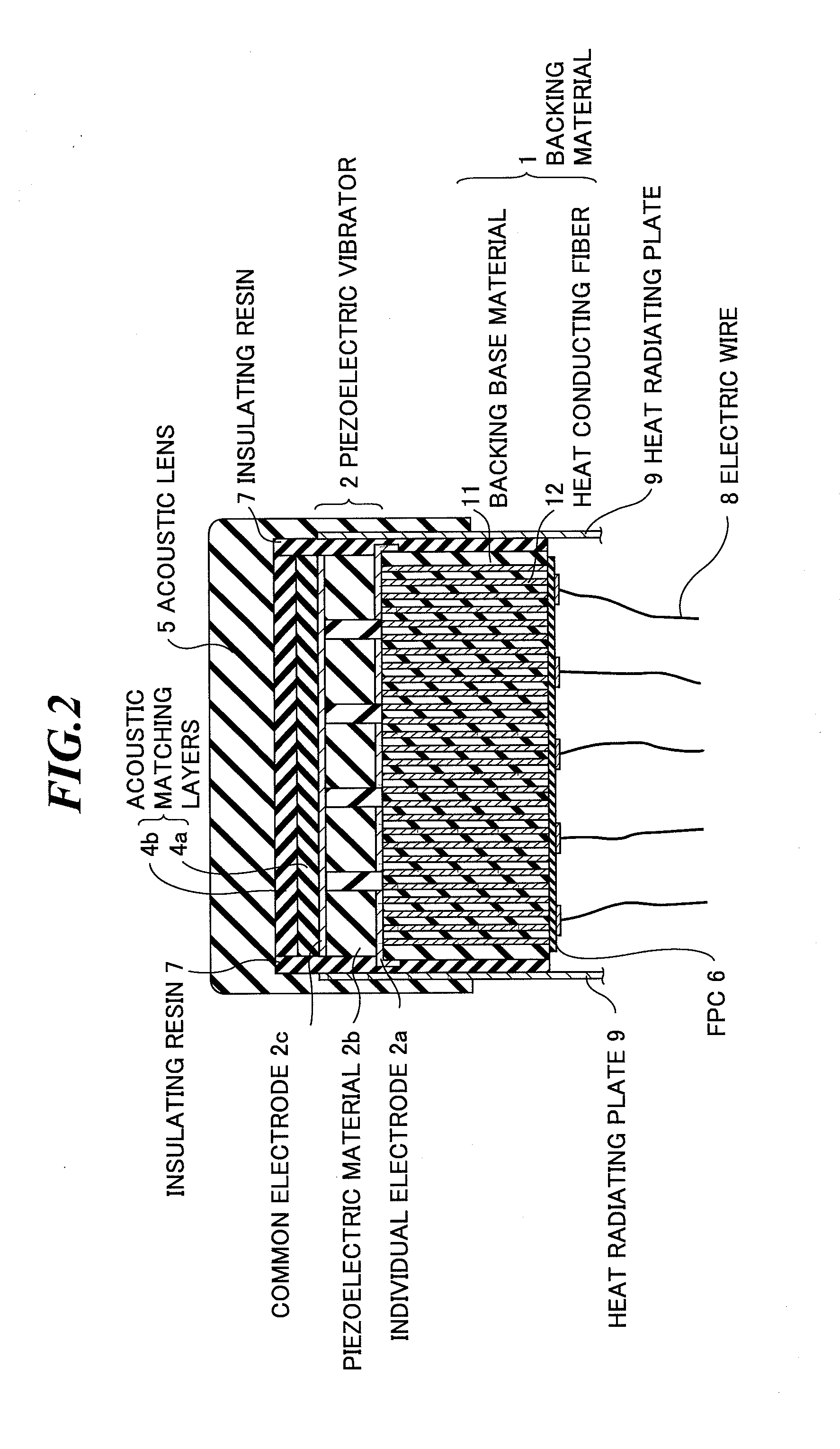
[0040]FIG. 1 is a perspective view schematically showing an internal structure of an ultrasonic probe according to the present invention, and FIG. 2 is a sectional view of the internal structure of the ultrasonic probe shown in FIG. 1 along a plane in parallel with the YZ-plane. The ultrasonic probe is used in contact with an object to be inspected when extracavitary scan is performed or used by being inserted into a body cavity of the object when intracavitary scan is performed.

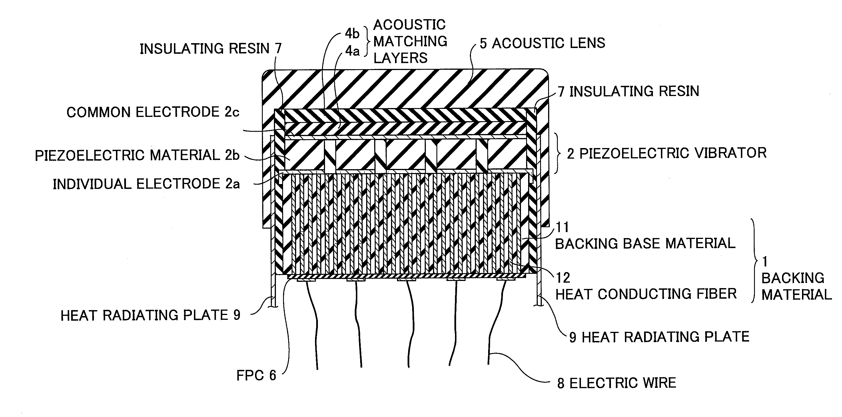
[0041]As shown in FIGS. 1 and 2, the ultrasonic probe has a backing material 1, one or plural ultrasonic transducers (piezoelectric vibrators) 2 provided on the backing material 1, resins 3 provided between those piezoelectric vibrators 2, one or plural acoustic matching layers (two acoustic matching layers 4a and 4b are shown in FIGS. 1 and 2) provided on the piezoelectric vibrators 2, an acoustic lens 5 provided on the acoustic matching layers according to need, two flexible printed circuit boards (FPCs) 6...

second embodiment

[0059]FIG. 5 is a sectional view showing an internal structure of the ultrasonic probe according to the present invention. As shown in FIG. 5, a piezoelectric vibrator 2 includes an individual electrode 2a formed on the backing material 1, a piezoelectric material 2b of PZT (Pb(lead) zirconate titanate) or the like formed on the individual electrode 2a, and a common electrode 2c formed on the piezoelectric material 2b. Typically, the common electrode 2c is commonly connected to the ground potential (GND).

[0060]In the second embodiment, the backing material 1 includes a backing base material 13 having electric insulation properties, and heat conducting fibers 14 having electric conductivity provided in the backing base material 13. Here, the heat conducting fibers 14 have higher heat conductivity than that of the backing base material 13. The individual electrode 2a of each piezoelectric vibrators 2 is electrically connected to two or more heat conducting fibers 14 having electric co...

fourth embodiment

[0073]FIG. 7 shows measurement results of surface temperature of the ultrasonic probe according to the present invention in comparison with those in a conventional case. The measurement was made by measuring the surface temperature of the acoustic lens in the air at a temperature of 23° C. FIG. 7 (a) shows a temperature distribution in the X-axis direction, which passes through the point of peak temperature on the surface of the acoustic lens, and FIG. 7 (b) shows a temperature distribution in the Y-axis direction, which passes through the point of peak temperature on the surface of the acoustic lens.

[0074]The peak temperature T3 on the surface of the acoustic lens of the ultrasonic probe using a conventional backing material containing no heat conducting fibers is 43° C., while the peak temperature T4 on the surface of the acoustic lens of the ultrasonic probe using the backing material containing heat conducting fibers according to the embodiment is 26° C. Accordingly, it is known...


PUM


Abstract

A backing material for suppressing the surface temperature rise of an ultrasonic probe. This backing material is provided on a back face of at least one vibrator for transmitting and/or receiving ultrasonic waves in an ultrasonic probe, and includes: a backing base material containing a polymeric material; and a heat conducting fiber provided in the backing base material, having a larger coefficient of thermal conductivity than that of the backing base material, and running through without disconnection from a first face of the backing material in contact with the at least one vibrator to a second face different from the first face.

Description

BACKGROUND OF THE INVENTION[0001]1. Field of the Invention[0002]The present invention relates to a backing material to be used in an ultrasonic probe for transmitting and receiving ultrasonic waves. Further, the present invention relates to an ultrasonic probe to be used when intracavitary scan or extracavitary scan is performed on an object to be inspected, and an ultrasonic endoscope to be used by being inserted into a body cavity of the object, each including such a backing material. Furthermore, the present invention relates to an ultrasonic diagnostic apparatus or ultrasonic endoscopic apparatus including such an ultrasonic probe or ultrasonic endoscope and a main body unit.[0003]2. Description of a Related Art[0004]In medical fields, various imaging technologies have been developed in order to observe the interior of an object to be inspected and make diagnoses. Especially, ultrasonic imaging for acquiring interior information of the object by transmitting and receiving ultras...

Claims


Application Information

Patent Timeline
IPC IPC(8): A61B8/00
CPCA61B8/12A61B8/445A61B8/4488A61B8/4455
Inventor HYUGA, HIROAKI
Owner FUJIFILM CORP
Why Eureka
Try Eureka