[0007]A delivery sheath holding the device is placed through the
introducer sheath that is already in the tissue tract and
femoral artery from the minimally
invasive procedure. When deployed the device closes the tissue tract and seals the puncture within the
femoral artery shut so that the patient does not bleed into the tissue tract and blood can resume normal flow through the
artery.
[0009]The closure device will have minimally a distal section for placing inside the interior opening of the vessel or cavity. The distal section is lodged in a delivery sheath to effect delivery to the vessel along the tissue tract that was already created with the
introducer sheath for the
percutaneous procedure. The delivery sheath has a proximal end at the
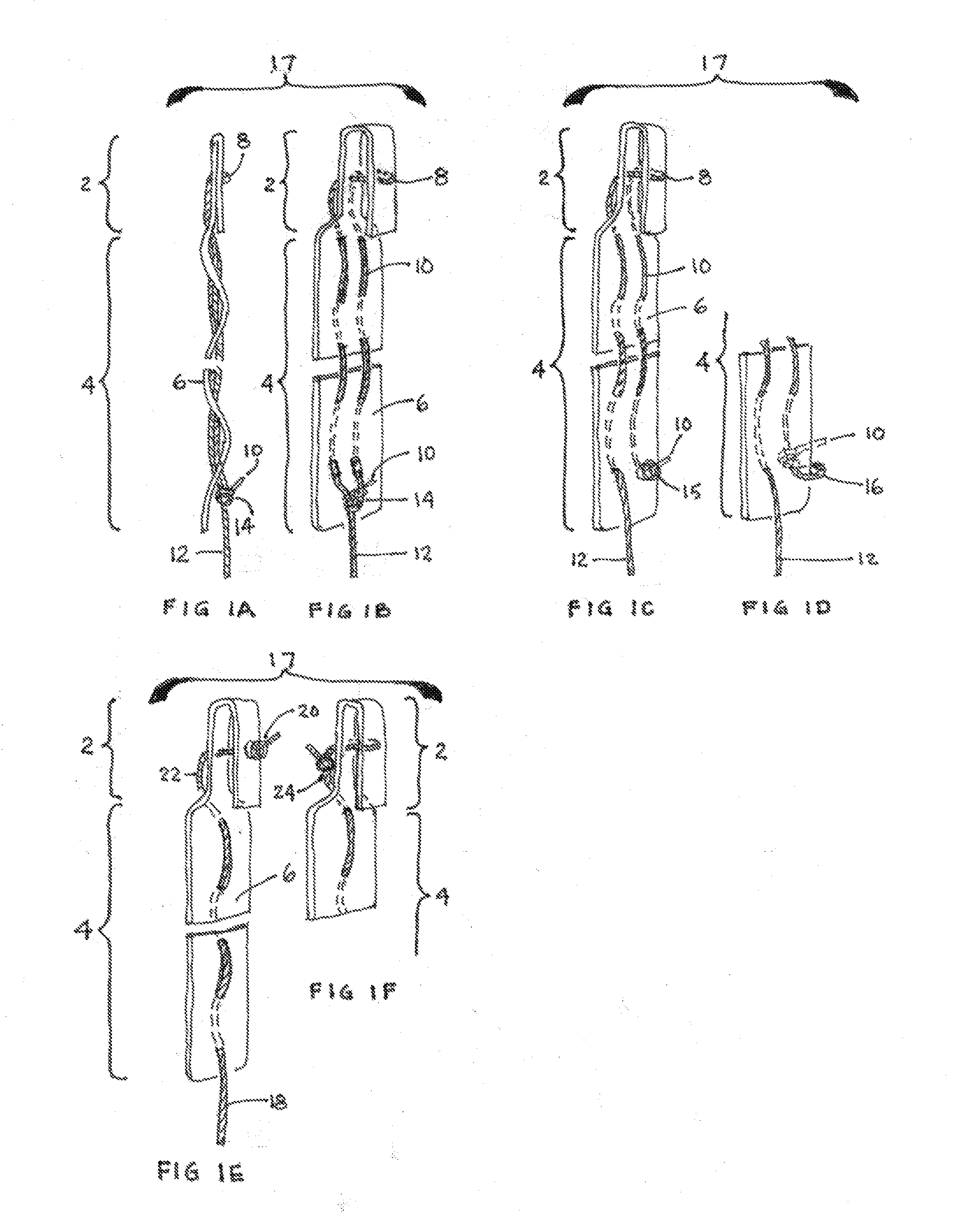
skin surface and a distal end close to the interior of the vessel or cavity where the distal section is to be delivered. The delivery sheath is capable of penetrating the wound along the length of the wound to pass through the interior opening of the vessel and release the distal section. The distal section is released using a
plunger that slides over a
tension member. The
tension member is affixed to the distal section and tension placed on the
tension member. The tension member is typically a suture or string or other type of strand or linear member able to withstand tension and it controls the placement and directionality and seating of the distal section at the vessel or
cavity wall, in coordination with the action of the
plunger in the delivery sheath that pushes the distal section out from the sheath while tension is placed on the distal section by pulling the tension member proximally toward the
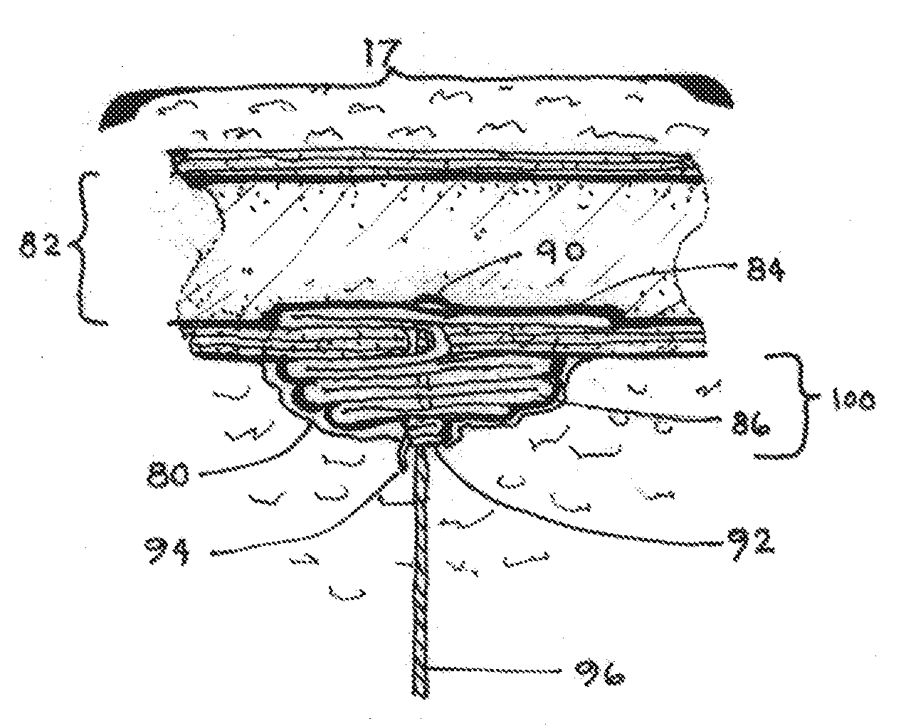
skin surface. In this manner a distal section having a stiff front end is released from the delivery sheath and rotated 90 degrees so that the stiff front end is now turned perpendicular to the opening of the delivery sheath, and is no longer parallel to it. The distal section of the device when seated in the vessel or
cavity wall provides resistance against the interior opening, allowing for the placement and adjustment of the rest of the device.
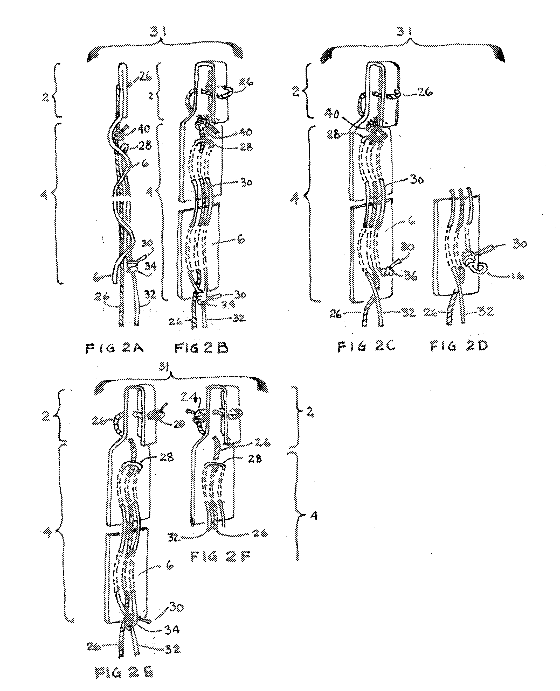
[0011]The configuration and placement of the tension member in the device can be important. The tension member can be a single string knotted at the distal section and threaded through the proximal section. Alternatively, the tension member can be looped through the distal section and proximal sections, effectively providing for two ends at the proximal section of the device near the
skin surface. In order to pull the looped tension member effectively, the tension member can be slip knotted to itself in the proximal section so that pulling on the string resulting from the slip knot
bunches the material as the slip knot travels down the device toward the distal section. This activity can be facilitated better using a
plunger that pushes the device away from the
skin surface and towards the vessel opening, while the tension member with its slip knot is pulled back towards the
skin surface to provide the tension necessary or positioning the distal section and bunching the proximal section.
[0012]Several configurations of the tension member can be used including that the tension member is looped through the distal section and proximal section using a single tension member having first and second proximal ends (ends residing at or near the
skin surface). The tension member can also pass through the distal section and the proximal section once and be knotted at said distal section, so that there is only a single end at the proximal section. A slip knot configuration of the tension member provides greater tension and control on the bunching material, and is achieved by having two ends of the same tension member (created when the tension member is threaded or looped through the material) then forming a slip knot with one of the ends around the other end so that pulling the single remaining thread of the slip knot causes the material to compress. The pulling of the tension member is usually done in coordination with the pushing of a plunger away from the skin and towards the vessel or cavity opening.
[0013]Another variation of the device includes a middle section positioned between the distal section and the proximal section. Although the middle section can be the same width as the proximal section, the middle section is optimally a narrow short section for passing from the vessel to the tissue tract. The middle section is connected to the distal section so that upon rotation of the distal section, the middle section remains exterior to the vessel or cavity, remaining in connection with the distal section. The middle section is optimally significantly narrower than the distal section (the rotated distal section) so as to provide minimal disturbance between the interior opening of the vessel or cavity and the tissue tract.
[0024]Yet another variation of the device provides that the device is as just described and additionally the short stiff front section bends at a midline after said long bunchable back section is bunched using the first tension member to withdraw the short stiff front section from the interior opening and bend it into the tissue tract in front of the long bunched back section, thereby clearing the vessel of the device and providing unobstructed fluid flow in the vessel.

