Device for Cleaning Exhaust Gas of Internal Combustion Engine

a technology for cleaning exhaust gas and internal combustion engines, which is applied in the direction of machines/engines, exhaust treatment electric control, separation processes, etc., can solve the problems of insufficient oxidation reaction, difficult to completely oxidize pm exhausted from the engine and remove the same, and worse fuel consumption, etc., to achieve excellent effect and effectively usable

Inactive Publication Date: 2009-03-12
TOYOTA JIDOSHA KK
View PDF10 Cites 23 Cited by
  • Summary
  • Abstract
  • Description
  • Claims
  • Application Information

AI Technical Summary

Benefits of technology

[0021]According to the present invention, an excellent effect is exhibited wherein ozone is effectively usable when PM is oxidized and cleaned by using ozone.

Problems solved by technology

However, there are problems in such proposals that if the fuel is forcibly injected, the fuel consumption becomes worse and DPF may be broken due to the rapid temperature rise of PM, that since the oxidation rate of PM caused by NO2 is insufficient in the proposal described in Japanese Patent Laid-Open No. 2002-531762, it is difficult to completely oxidize PM exhausted from the engine and remove the same, and that since both the catalyst and PM are solid in the proposal described in Japanese Patent Laid-Open Nos. 6-272541 and 9-125931, the both are not into desirably contact with each other to result in the insufficient oxidation reaction.
However, in the technology disclosed in Japanese Patent Laid-Open No. 2005-502823, ozone is generated from oxygen that is one of components of the exhaust gas by using plasma and introduced into the particulate filter together with the exhaust gas containing NOx or others whereby an amount of ozone thus generated is insufficient.
Also, there is a risk in that the ozone having a large oxidation capacity may react with NOx or others in the exhaust gas and is consumed prior to being introduced into the particulate filter, resulting in the reduction of the amount of ozone usable for oxidizing and removing PM, which is problematic since the cleaning efficiency becomes lower and the oxidation rate of PM decreases.

Method used


Image

  • Device for Cleaning Exhaust Gas of Internal Combustion Engine
  • Device for Cleaning Exhaust Gas of Internal Combustion Engine
  • Device for Cleaning Exhaust Gas of Internal Combustion Engine

Examples


first embodiment

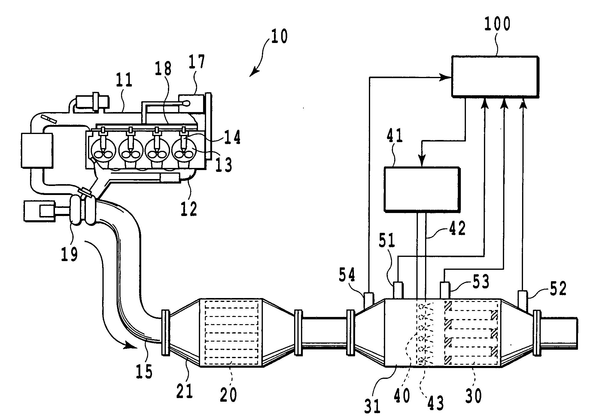
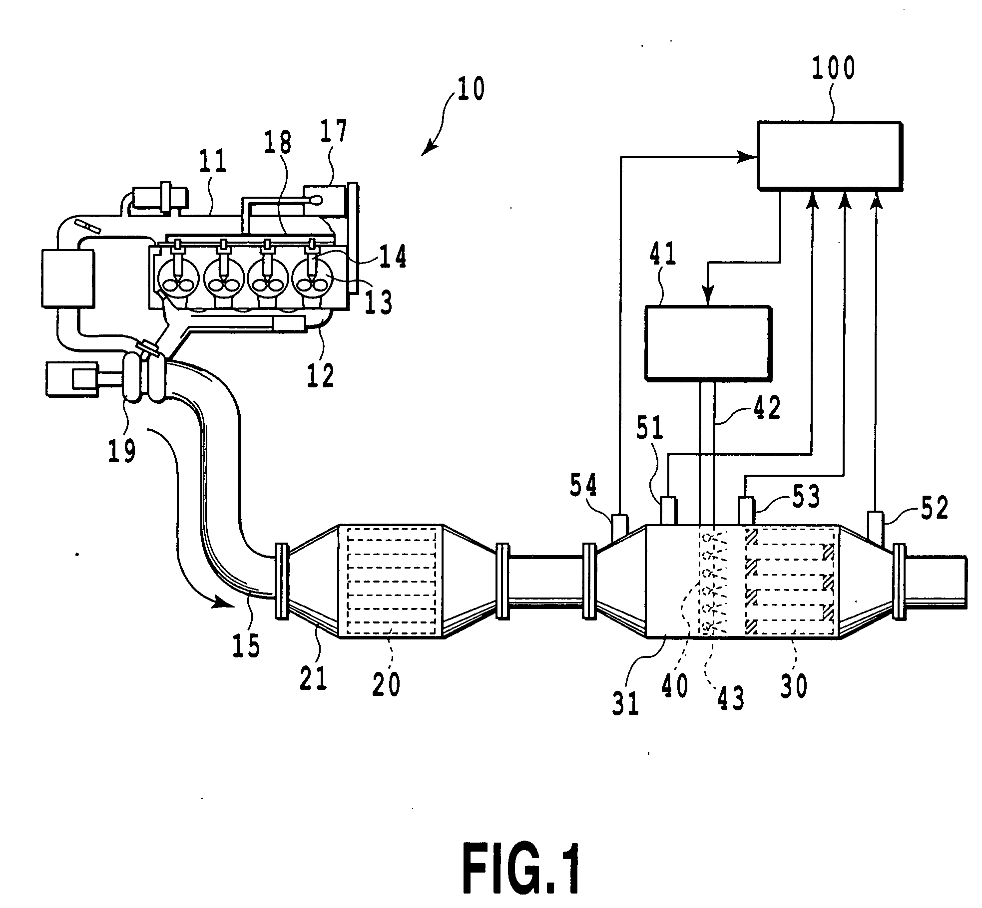
[0041]FIG. 1 diagrammatically illustrates a system of a device for cleaning exhaust gas of an internal combustion engine according to a first embodiment of the present invention, wherein reference numeral 10 denotes a compression ignition type internal combustion engine; i.e., a diesel engine, 11 denotes an intake manifold communicated with an intake port, 12 denotes an exhaust manifold communicated with an exhaust port, and 13 denotes a combustion chamber. According to this embodiment, fuel supplied from a fuel tank not shown to a high pressure pump 17 is sent thereby to a common rail 18 and stored there under a high pressure. The highly pressed fuel in the common rail 18 is directly injected from a fuel injection valve 14 to the combustion chamber 13. Exhaust gas from the diesel engine 10 flows via the exhaust manifold 12 and a turbocharger 19 and reaches an exhaust gas passage 15 provided downstream thereof, wherein the exhaust gas is cleaned and discharged to an outer air. In th...

second embodiment

[0099]Next, a second embodiment according to the present invention will be described with reference to the attached drawings. In this regard, the same reference numerals are used in the drawings for denoting the same parts as those in the first embodiment, and the detailed explanation thereof will be eliminated.

[0100]FIG. 10 diagrammatically illustrates a system of a device for cleaning exhaust gas of an internal combustion engine according to the second embodiment. As illustrated, in the second embodiment, second ozone feeding nozzles 90 are provided as separate means for feeding ozone (O3) in an exhaust gas passage 15 on the upstream side from NOx catalyst. The second ozone feeding nozzles 90 are of the same structure as the ozone feeding nozzles 40 disposed upstream from DPF 30. The second ozone feeding nozzles 90 and the ozone feeding nozzles 40 are connected to a flow rate control unit 91, and the flow rate control unit 91 is connected to the ozone generator 41. The flow rate c...

third embodiment

[0128]Next, a third embodiment according to the present invention will be described with reference to the attached drawings. In this regard, the same reference numerals are used in the drawings for denoting the same parts as those in the first embodiment, and the detailed explanation thereof will be eliminated.

[0129]FIG. 15 diagrammatically illustrates a system of a device for cleaning exhaust gas of an internal combustion engine according to the second embodiment. As illustrated, in the third embodiment, an oxidation catalyst 110 is disposed in a casing 21 common to the NOx catalyst 20.

[0130]In the first embodiment, as described before, when the NOx catalyst 20 is of a storage reduction type, the rich spike (the separate injection or the post injection of gas oil) is executed for releasing or reduction-cleaning NOx stored in the NOx catalyst 20. Alternatively, if such rich spike is not executed, HC in the exhaust gas passes through the NOx catalyst 20 with substantially no interfer...


PUM

PropertyMeasurementUnit
temperatureaaaaaaaaaa
concentrationaaaaaaaaaa
structureaaaaaaaaaa

Abstract

A device for cleaning exhaust gas of an internal combustion engine according to the present invention includes a device (30) for collecting particulate matter from exhaust gas in an exhaust gas passage (15), ozone feeding device (40) capable of feeding ozone to the device (30) for collecting particulate matter from upstream thereof, and an NOx catalyst (20) disposed upstream from the ozone feeding device (40), for cleaning NOx in the exhaust gas. Since NOx is preliminarily removed by the NOx catalyst (20) at apposition upstream from the ozone feeding device (40), the consumption of ozone due to the reaction with NOx is prevented, whereby it is possible to effectively use ozone for the purpose of oxidizing and removing PM in the device (30) for collecting particulate matter.

Description

TECHNICAL FIELD[0001]The present invention relates to a device for cleaning exhaust gas of an internal combustion engine, particularly to a device for cleaning exhaust gas exhausted from a diesel engine by collecting and oxidizing particulate matter in the exhaust gas.BACKGROUND ART[0002]Generally, it has been known that in exhaust gas exhausted from a diesel engine, particulate matter (referred to as PM hereinafter) mainly composed of carbon is contained and causes the atmospheric contamination. Accordingly, many devices and / or methods have been proposed for collecting such particulate matter and removing the same from the exhaust gas.[0003]For example, there are proposals in that a temperature of a diesel particulate filter (DPF) is made to rise by forcibly injecting fuel so that the collected PM is oxidized and burnt, or that NO2 is generated from NO in the exhaust gas so that PM is oxidized by NO2 (see, for example, Japanese Patent Laid-Open No. 2002-531762), or that PM is oxidi...

Claims


Application Information

Patent Timeline
Patent Type & Authority Applications(United States)
IPC IPC(8): F01N9/00
CPCB01D53/9431F01N13/009B01D2251/104F01N3/023F01N3/035F01N3/0821F01N3/0842F01N3/103F01N3/106F01N3/206F01N9/00F01N2240/38F01N2250/02F01N2250/14F01N2560/026F01N2560/06F01N2570/14F01N2610/08F01N2610/14F01N2610/146F01N2900/0408F01N2900/1402F01N2900/1602Y02T10/47F01N13/0097B01D53/944Y02T10/40Y02A50/20B01D53/86F01N3/02F01N3/08F01N3/24
Inventor HIRATA, HIROHITOKAKINOHANA, MASARUIBE, MASAYASAKAKIBARA, YUJIITOH, YOSHIHIKO
Owner TOYOTA JIDOSHA KK
Why Eureka
Try Eureka