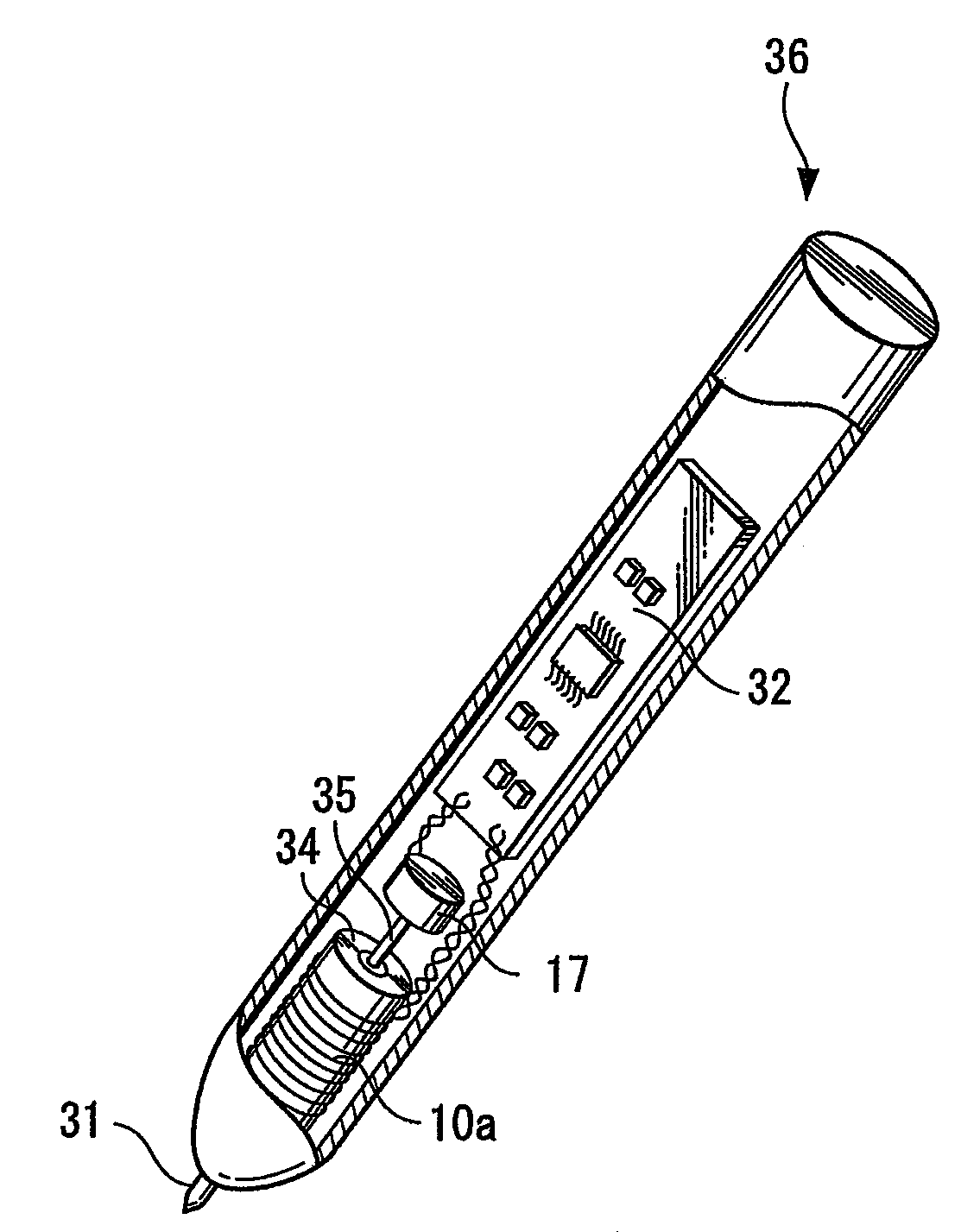
Position indicator

a technology of position indicator and position indicator, which is applied in the direction of reference comparison, ac/dc measuring bridge, instruments, etc., can solve the problems of increasing power consumption, reducing sampling speed, and high cost of the whole pen-tablet device, and achieves high resolution and rapid detection in a short period of time.

Active Publication Date: 2009-03-12
WACOM CO LTD
View PDF3 Cites 47 Cited by
  • Summary
  • Abstract
  • Description
  • Claims
  • Application Information

AI Technical Summary

Benefits of technology

[0012]According to various exemplary embodiments of the present invention, since the detection voltage used by the voltage comparison circuit is switched at the same time as the time constant (or, more specifically, the variable range of the time constant) of the time-constant circuit is switched, it is not necessary to perform an operation for predetermining the first measured value (T1) (i.e., the time at which to switch from one time constant to the other time constant), and therefore a continuous variable can be rapidly detected in a short period of time and in high resolution.

Problems solved by technology

If the frequency is increased, the pen-tablet device as a whole will become expensive, and also the power consumption will be increased.
However, according to Japanese Unexamined Patent Application Publication No. 2005-165768, since a measurement involving charging or discharging is performed twice (during the switching-timing predetermination measurement and an actual measurement), longer time is required, and further, the sampling speed will decrease if detection is performed in high resolution.

Method used


Image

  • Position indicator
  • Position indicator
  • Position indicator

Examples


Embodiment Construction

)

[0020]In the present invention, a device disclosed in Japanese Unexamined Patent Application Publication No. 2005-165768 has been improved, and the detection voltage used to detect whether or not a voltage output from a time-constant circuit is equal to or higher than a predetermined value is switched between two values.

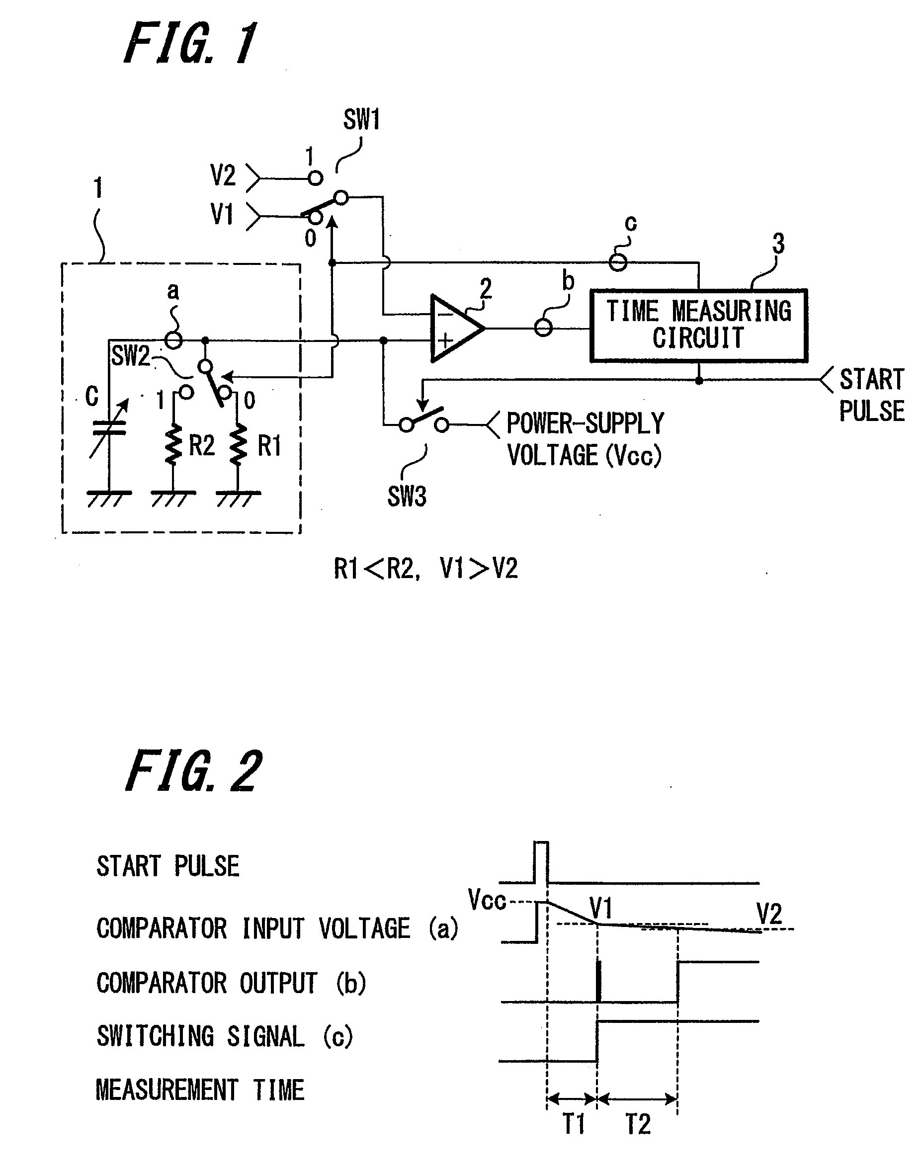
[0021]The basic principle of the present invention will be described below with reference to FIG. 1 and FIG. 2.

[0022]FIG. 1 is a circuit diagram showing a basic configuration for detecting a continuous variable according to one embodiment of the present invention. As shown in FIG. 1, a non-inversion input terminal of a comparator 2 is connected to a time-constant circuit 1, which includes a variable capacitor C and resistors (R1, R2). The time constant of the time-constant circuit 1 can be switched between two types (i.e., two variable ranges), based on switching between the resistor R1 and the resistor R2.

[0023]The above-described configuration is identical to that...


PUM


Abstract

When a start pulse is supplied, a time-constant circuit (1) is charged to a voltage Vcc, and charge in a variable capacitor (C) is discharged through a resistor (R1). Upon the voltage (a) of the variable capacitor (C) reaching a preset reference voltage V1, a signal (b) is output from a comparator (2). In response to the signal (b), a time measuring circuit (3) stores a measured time period as a time period “T1”, and at the same time a switching signal (c) is output. The switching signal (c) switches the reference voltage V1 to a reference voltage V2, which is slightly lower than the reference voltage V1, and further switches the resistor R1 to a resistor R2, which has higher resistance than the resistor R1. Upon the voltage (a) of the variable capacitor (C) reaching the reference voltage V2, the signal (b) is output from the comparator 2. In response to the signal (b), the time measuring circuit (3) stores a measured time period as a time period “T2”.

Description

CROSS REFERENCES TO RELATED APPLICATIONS[0001]The present application claims priority under 35 U.S.C. §119 from Japanese Patent Application JP 2007-235966 filed in the Japanese Patent Office on Sep. 11, 2007, the entire contents of which is incorporated herein by reference.BACKGROUND OF THE INVENTION[0002]1. Field of the Invention[0003]The present invention relates to a position indicator, such as a stylus pen, capable of detecting operational information represented by a continuous variable and transmitting the detected operational information to a tablet. Description of the Related Art:[0004]Examples of known position indicators are disclosed in Japanese Unexamined Patent Application Publication No. H07-175572, corresponding to U.S. Pat. No. 5,679,930, incorporated by reference herein. According to Japanese Unexamined Patent Application Publication No. H07-175572, operational information represented by a continuous variable, such as pen pressure, drawing line width, color / darkness...

Claims


Application Information

Patent Timeline
Patent Type & Authority Applications(United States)
IPC IPC(8): G06K11/06
CPCG06F3/046G06F3/03545
Inventor KATSURAHIRA, YUJI
Owner WACOM CO LTD
Why Eureka
Try Eureka