
Gasoline-ethanol separation apparatus

a technology of gasoline and ethanol, which is applied in the direction of separation process, other chemical processes, liquid displacement, etc., can solve the problems of narrow operation region capable of stably operating the engine, difficult control, flame off, etc., and achieve the effect of simple structur

Inactive Publication Date: 2009-03-12
HONDA MOTOR CO LTD
View PDF13 Cites 62 Cited by
  • Summary
  • Abstract
  • Description
  • Claims
  • Application Information

AI Technical Summary

Benefits of technology

[0025]The present invention is designed with respect to the above described circumstances, and is directed at providing a gasoline-ethanol separation apparatus for separating gasoline and ethanol from a mixture fuel formed of mixed gasoline and ethanol with a simple structure.
[0026]The present invention is also directed at providing a gasoline-ethanol separation apparatus which has a simple structure and is used for an internal combustion engine.
[0031]Accordingly, the gasoline-ethanol separation apparatus according to the present invention can separate a mixture fuel formed of mixed gasoline and ethanol into the gasoline and an ethanol-water mixture liquid, and can take out the separated gasoline and the ethanol-water mixture liquid, with a simpler structure compared to a conventional gasoline-ethanol separation apparatus.
[0034]In the above described separation tank, the storage quantity of the above described gasoline decreases due to the above described returning operation. On the other hand, the above described mixture fuel is newly supplied to the separation tank. Then, the above described mixture fuel which has been newly supplied is separated into the above described gasoline and the above described ethanol-water mixture liquid, so that the storage quantity of the ethanol-water mixture liquid relatively increases to consequently elevate the above described interface to a higher position than that of the above described predetermined position. Thus, the gasoline-ethanol separation apparatus according to the present invention can resolve the deviation of storage quantity occurring in the above described gasoline and the above described ethanol-water mixture liquid in the above described separation tank, by returning the above described gasoline stored in the above described separation tank to the above described fuel tank with the use of the above described gasoline-returning means.

Problems solved by technology

However, the compression ignition internal combustion engine has difficulty in controlling the timing of ignition in contrast to a spark ignition type internal combustion engine, and has a problem that the operation region capable of stably operating the engine is narrow.
More particularly, the above described compression ignition internal combustion engine has a problem of easily causing knocking when a high load is required to the engine which uses fuel with high ignitability, and easily causing flame off when a low load is required to the engine which uses fuel with low ignitability.
Accordingly, the above described liquid hydrocarbon-ethanol separation apparatus unavoidably makes the weight of the whole apparatus large.
However, the above described liquid hydrocarbon-ethanol separation apparatus still comprises 5 tanks, so that the whole apparatus unavoidably becomes large.
The liquid hydrocarbon-ethanol separation apparatus also combines a switching operation of four air open valves, a switching operation of four liquid-supply on-off valves and a switching operation of three air-suction on-off valves to supply fuel or water by using a difference among internal pressures of a fuel tank of a supply source, a water tank and a fuel tank of a receiving side, so that the structure and the control unavoidably become complicated.

Method used


Image

  • Gasoline-ethanol separation apparatus
  • Gasoline-ethanol separation apparatus
  • Gasoline-ethanol separation apparatus

Examples


Embodiment Construction

[0040]Next, embodiments according to the present invention will now be described in more detail with reference to the attached drawings.

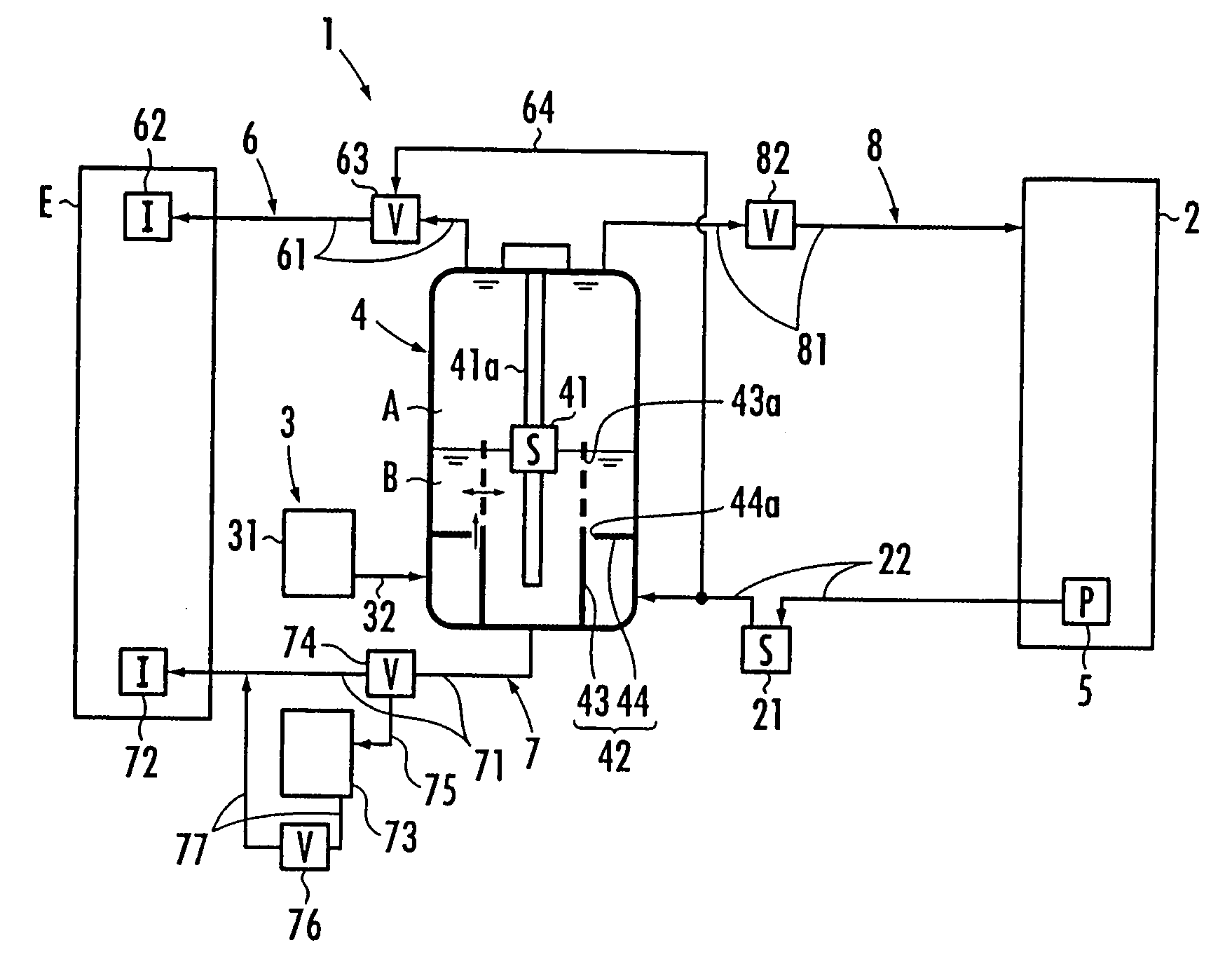
[0041]A gasoline-ethanol separation apparatus 1 according to the present embodiment illustrated in FIG. 1 is an apparatus for mixing water with a mixture fuel of mixed gasoline and ethanol to separate the resultant liquid into gasoline and an ethanol-water mixture liquid, and is used for a compression ignition internal combustion engine (hereinafter referred to as engine) E, for instance. The engine E uses gasoline as its fuel when a low load is required, and uses a mixture of the gasoline and an added ethanol-water mixture liquid as its fuel when a high load is required.

[0042]The gasoline-ethanol separation apparatus 1 comprises: a fuel tank 2 for accommodating a mixture fuel of mixed gasoline and ethanol; water-supply means 3 for supplying water to be mixed to the mixture fuel; and a separation tank 4 for separating the fuel into gasoline (A) and ...


PUM

PropertyMeasurementUnit
Flow rateaaaaaaaaaa
Concentrationaaaaaaaaaa
Shapeaaaaaaaaaa

Abstract

This present invention provides a gasoline-ethanol separation apparatus which is used for an internal combustion engine, has a simple structure, and can separate a mixture fuel formed of mixed gasoline and ethanol into gasoline and ethanol. The gasoline-ethanol separation apparatus 1 includes a fuel tank 2 for accommodating a mixture fuel, a separation tank 4 for separating the mixture fuel supplied from the fuel tank 2 into the gasoline (A) and an ethanol-water mixture liquid (B), by mixing water supplied by water-supply means 3 with the mixture fuel, and storing the separated gasoline (A) and ethanol-water mixture liquid (B); pressurizing means 5 for pressurizing the gasoline (A) and the ethanol-water mixture liquid (B) in the separation tank 4 through the mixture fuel to be supplied into the separation tank 4; gasoline-taking-out means 6 for taking the gasoline (A) out from an upper part of the interface between the gasoline (A) and the ethanol-water mixture liquid (B) in the separation tank 4 to the outside of the separation tank 4 through a first on-off valve 62; and ethanol-taking-out means 7 for taking the ethanol-water mixture liquid (B) in the separation tank 4 out from a lower part of the interface to the outside of the separation tank 4 through a second on-off valve 72.

Description

BACKGROUND OF THE INVENTION[0001]1. Field of the Invention[0002]The present invention relates to a gasoline-ethanol separation apparatus for separating a mixture fuel formed of mixed gasoline and ethanol into gasoline and an ethanol-water mixture liquid by mixing water with the mixture fuel.[0003]2. Description of the Related Art[0004]In recent years, a compression ignition internal combustion engine represented by a homogeneous charge compression ignition internal combustion engine has been investigated so as to enhance a fuel efficiency of an internal combustion engine and reduce emissions. The compression ignition internal combustion engine is an engine of introducing an oxygen-containing gas and a compression self-ignitable fuel into a cylinder, and compressing the mixture gas to self-ignite the mixture gas.[0005]However, the compression ignition internal combustion engine has difficulty in controlling the timing of ignition in contrast to a spark ignition type internal combusti...

Claims


Application Information

Patent Timeline
IPC IPC(8): C07C29/86B01D11/04
CPCB01D11/0488B01D11/0492
Inventor KAMIO, JUNICHIKUBO, YASUYUKI
Owner HONDA MOTOR CO LTD
Features
  • Generate Ideas
  • Intellectual Property
  • Life Sciences
  • Materials
  • Tech Scout
  • Unparalleled Data Quality
  • Higher Quality Content
  • 60% Fewer Hallucinations
Learn More