Methods and apparatus for improved ejection head planarity and reduced ejection head damage

a technology of ejection head and planarity, applied in printing and other directions, can solve the problems of chip cracking, product yield loss, and increase so as to minimize chip cracking and warpage, the chip size increases, and the difficulty of handling chips without damage or breakage increases.

Inactive Publication Date: 2009-03-12
FUNAI ELECTRIC CO LTD
View PDF1 Cites 11 Cited by
  • Summary
  • Abstract
  • Description
  • Claims
  • Application Information

AI Technical Summary

Benefits of technology

[0005]Attaching the chips to the body and curing the adhesive is a delicate procedure and may result in chip cracking and thus product yield loss. As the size of the chips increase, the difficulty associated with handling the chips without damage or breakage also increases. Larger chips require even more care when attaching the chips to a thermoplastic body so as to minimize chip cracking and warpage.
[0006]It is believed that a predominant contributor of chip warpage is the coefficient of thermal expansion mismatch between the chip and the thermoplastic body. During manufacturing, when the chip and body go through the adhesive cure cycle, chip warpage is introduced as the components cool. If the displacement for the chip from a planar configuration is too large, the chip cracks. Accordingly, there continues to be a need for improved manufacturing processes and techniques which provide improved ejection head components and structures without product loss due to chip cracking.
[0007]With regard to the above, there is provided a micro-fluid ejection head assembly having improved assembly characteristics and methods of manufacturing a micro-fluid ejection head assembly. The micro-fluid ejection head includes a fluid supply body having at least one fluid supply port in a recessed area therein. A reinforcing member circumscribes the fluid supply port. A micro-fluid ejection head is attached with an adhesive to the supply body in the recessed area so that cracking of the ejection head during adhesive curing is substantially reduced.
[0008]In another embodiment, there is provided a method for improving micro-fluid ejection assembly yield. The method includes providing a fluid supply body having a fluid supply port in a recessed area thereof therein and a reinforcing member circumscribing the fluid supply port. A micro-fluid ejection head is adhesively attached to the fluid supply body in the recessed area. The method may provide a substantially improved yield of usable micro-fluid ejection assemblies.
[0009]An advantage of the foregoing structure and method therefor is that chip warpage and thus chip cracking may be substantially reduced without the need to select materials having similar coefficients of thermal expansion. The structures and methods provided herein may be used with a wide variety of thermoplastic body materials and chip substrate materials to reduce warpage of the chip substrate during adhesive curing cycles. A wider variety of stiffener materials may be used with the thermoplastic bodies to maintain substantially lower chip warpage as compared to materials selected for a coefficient of thermal expansion that is similar to the coefficient of thermal expansion of the chip material

Problems solved by technology

Attaching the chips to the body and curing the adhesive is a delicate procedure and may result in chip cracking and thus product yield loss.
As the size of the chips increase, the difficulty associated with handling the chips without damage or breakage also increases.
It is believed that a predominant contributor of chip warpage is the coefficient of thermal expansion mismatch between the chip and the thermoplastic body.
During manufacturing, when the chip and body go through the adhesive cure cycle, chip warpage is introduced as the components cool.
If the displacement for the chip from a planar configuration is too large, the chip cracks.

Method used


Image

  • Methods and apparatus for improved ejection head planarity and reduced ejection head damage
  • Methods and apparatus for improved ejection head planarity and reduced ejection head damage
  • Methods and apparatus for improved ejection head planarity and reduced ejection head damage

Examples


example 1

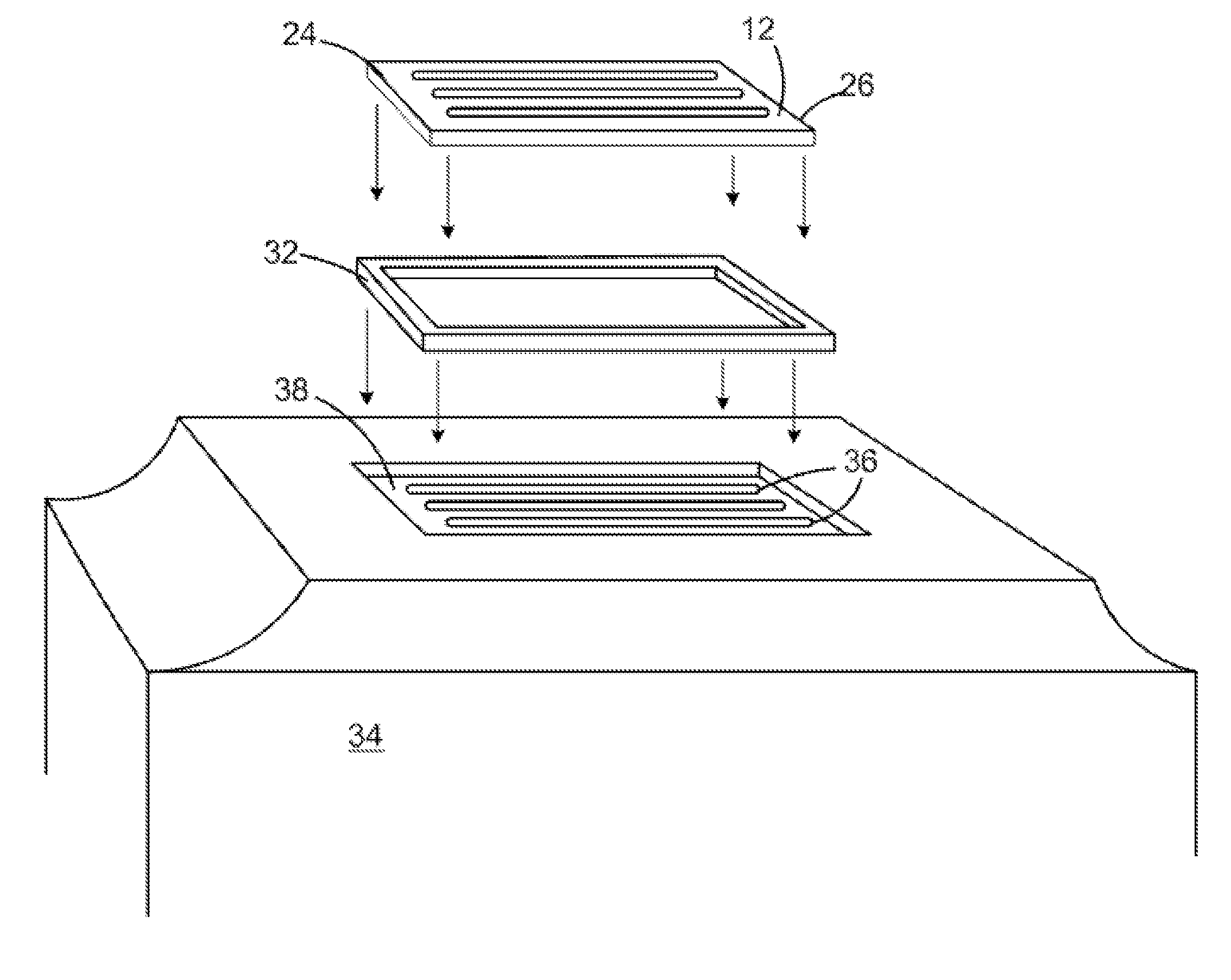
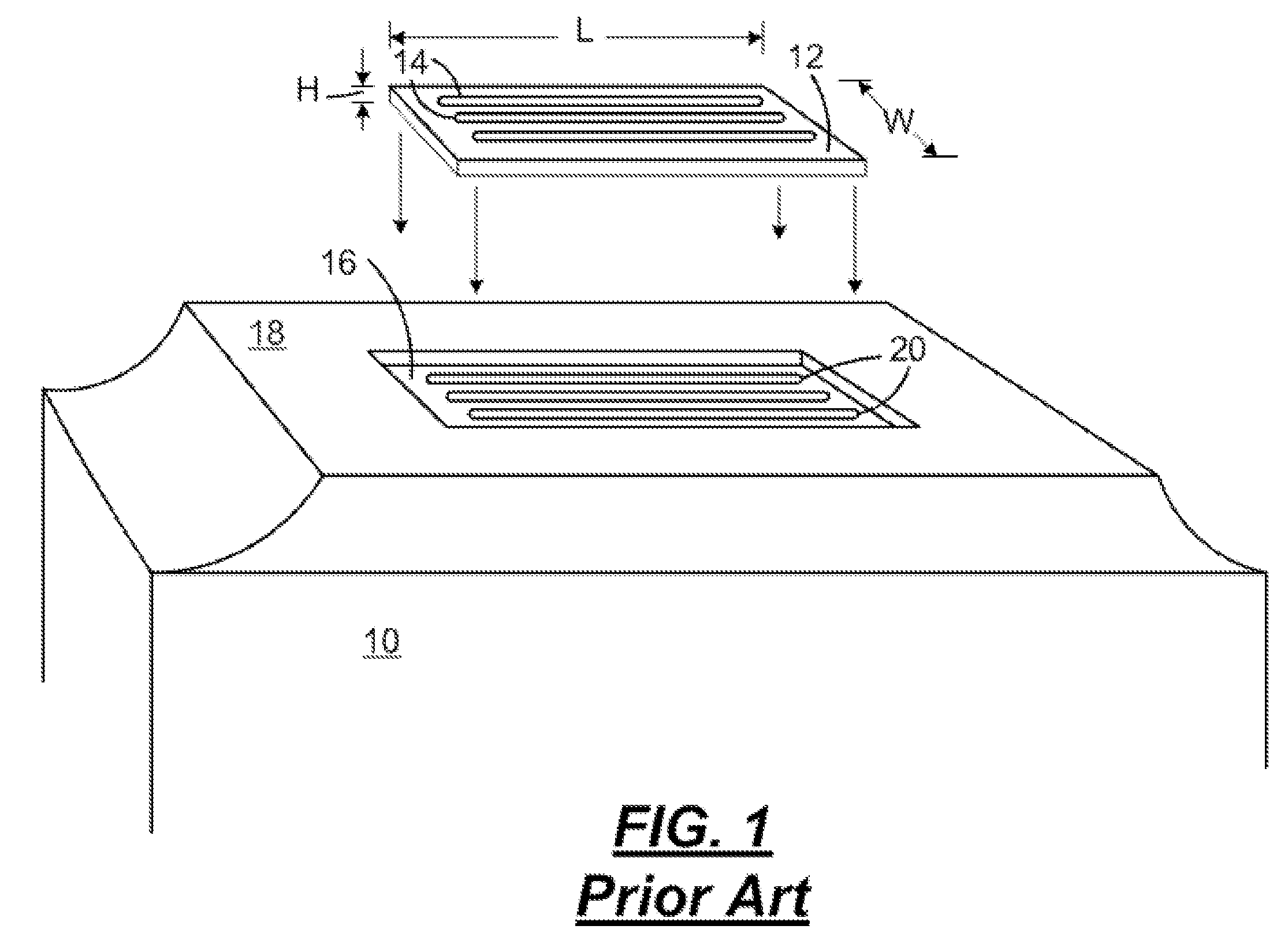
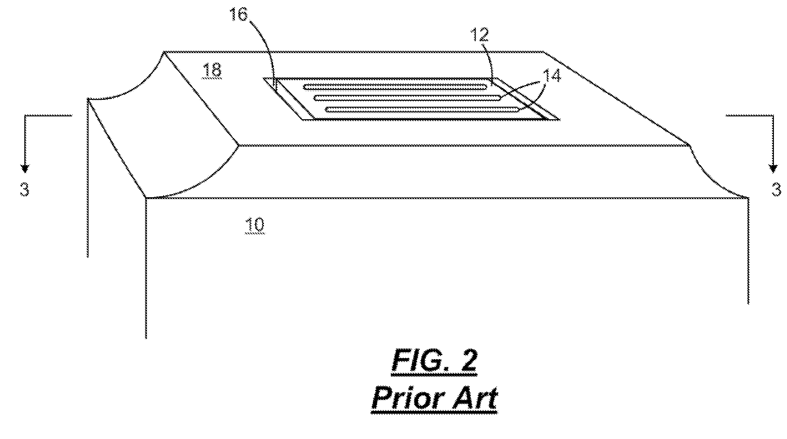
[0033]A comparison of the amount of chip bowing for a prior art body, a body having a compliant chip pocket and a body containing a reinforcing member is given in the following table. The amount of bowing in the prior art chip pocket (FIGS. 1-4) is used as a baseline for comparing other chip pocket designs. In the table, the maximum distance between of the centerlines 28 and 30 is used as the maximum substrate bowing in the table for each of the indicated chip pocket designs at a 60° temperature difference applied for adhesive curing. A steel reinforcing member 32 is used to reinforce the chip pocket for the rigid chip pocket design.

TABLE 1Max. BowingChip Pocket Design(microns)% decrease / increasePrior art chip pocket (FIGS. 1-4)10BaselineCompliant chip pocket1330% increaseRigid chip pocket (FIGS. 5-8)640% decrease

[0034]From the foregoing table, it is evident that use of a substantially rigid reinforcing ring 32 in the chip pocket 38 of the body 34 provides a substantial decrease in ...

example 2

[0035]In the following example, an effect of the use of glass fiber reinforcing of the chip pocket 38 and the use of different thicknesses of ceramic reinforcing members 32 is compared. The adhesive curing conditions were the same as in Example 1.

TABLE 2Max.Min.Delta deflectiondeflectiondeflection(Max. − Min)Configuration(microns)(microns)(microns)Prior art chip pocket28.516.512FIGS. (1-4)Prior art chip pocket13.88.55.36(20 wt. % glass filled)Prior art chip pocket8.75.443.26(30 wt. % glass filled)0.6 mm thin ceramic9.55.34.2ring (20 wt. % glassfilled)1.2 mm thick ceramic8.84.44.4ring (20 wt. % glassfilled)1.2 mm thick ceramic146.57.5ring (0 wt. % glass filled)

[0036]As shown by the foregoing example, reinforcing the chip pocket with 20 wt. % glass fiber fill, 30 wt. % fiberglass and / or a ceramic ring or a combination of ceramic ring and glass fiber fill is effective in substantially reducing the delta deflection of the body and substrate during an adhesive curing procedure for attach...

example 3

[0037]In the following example, an effect of the use of the substrate thickness on the bowing characteristics is compared. The adhesive curing conditions were the same as in Example 1.

TABLE 3Max.Min.Delta deflectiondeflectiondeflection(Max. − Min)Configuration(microns)(microns)(microns)Prior art chip pocket13.88.55.36450 micron thick substrate12(20 wt. % glass filled)Prior art chip pocket8.75.443.26450 micron thick substrate12(30 wt. % glass filled)0.6 mm thin ceramic ring9.55.34.2(20 wt. % glass filled)Prior art chip pocket0.9250.450.5450 micron thick substrate12(20 wt. % glass filled)Prior art chip pocket13.58.55.0625 micron thick substrate12 (20 wt. % glass filled)

[0038]As illustrated by the foregoing table, increasing the thickness of the substrate 12 has little impact on the delta deflection amount of the substrate during adhesive curing. However, the glass fiber filled chip pockets and chip pockets containing ceramic rings have substantially improved delta deflection amount. T...


PUM


Abstract

A micro-fluid ejection head assembly having improved assembly characteristics and methods of manufacturing a micro-fluid ejection head assembly. The micro-fluid ejection head includes a fluid supply body having at least one fluid supply port in a recessed area therein. A reinforcing member circumscribes the fluid supply port. A micro-fluid ejection head is attached with an adhesive to the supply body in the recessed area so that cracking of the ejection head during adhesive curing is substantially reduced.

Description

TECHNICAL FIELD[0001]The disclosure relates to micro-fluid ejection head structures and in particular to apparatus and methods that are effective for improving the planarity of ejection heads and reducing ejection head damage.BACKGROUND AND SUMMARY[0002]Micro-fluid ejection heads for micro-fluid ejection devices such as ink jet printers continue to be improved as the technology for making the ejection heads continues to advance. New techniques are constantly being developed to provide low cost, highly reliable micro-fluid ejection head structures that can be manufactured in high yield with a relatively low amount of spoilage or ejection head damage.[0003]In order to increase ejection head speed and volume output, larger ejection heads having an increased number of ejection actuators are being developed. However, as the ejection head size and number of ejection actuators increases, manufacturing apparatus and techniques are required to meet increased tolerance demands for such ejecti...

Claims


Application Information

Patent Timeline
Patent Type & Authority Applications(United States)
IPC IPC(8): B41J2/04B41J2/16B41J2/14
CPCB41J2/1601B41J2002/14362B41J2/1637B41J2/1623
Inventor MULAY, SHIRISH PADMAKARRAMAKRISHNAN, BHASKAR
Owner FUNAI ELECTRIC CO LTD
Why Eureka
Try Eureka