Rectifier Circuit and Three-Phase Rectifier Device

a rectifier device and rectifier circuit technology, applied in the direction of dc-dc conversion, climate sustainability, dc-dc conversion, etc., can solve the problems of complicated configuration of the device for injecting current into the interphase reactor, increase the possibility of overheating or breaking of phase advance capacitors and transformers of power systems,

Inactive Publication Date: 2009-03-12
DAIKIN IND LTD
View PDF3 Cites 38 Cited by
  • Summary
  • Abstract
  • Description
  • Claims
  • Application Information

AI Technical Summary

Benefits of technology

[0012]The present invention has been made by considering the problems above, and an object of the present invention is to provide a technique by which currents flowing in a transformer for outputting plural sets of three-phase currents given to a multiple rectifier circuit are easily made close to sinusoidal waves.

Problems solved by technology

This increases the possibility of overheating or breakage of phase advance capacitors and transformers of power systems due to the harmonic current.
However, injecting a current into an interphase reactor with an additional coil, as described in Non-Patent Document 2, requires applying a complicated waveform to the coil.
Also, the device for injecting current into the interphase reactor is configured complicatedly, or a separate voltage source is required.

Method used


Image

  • Rectifier Circuit and Three-Phase Rectifier Device
  • Rectifier Circuit and Three-Phase Rectifier Device
  • Rectifier Circuit and Three-Phase Rectifier Device

Examples


first preferred embodiment

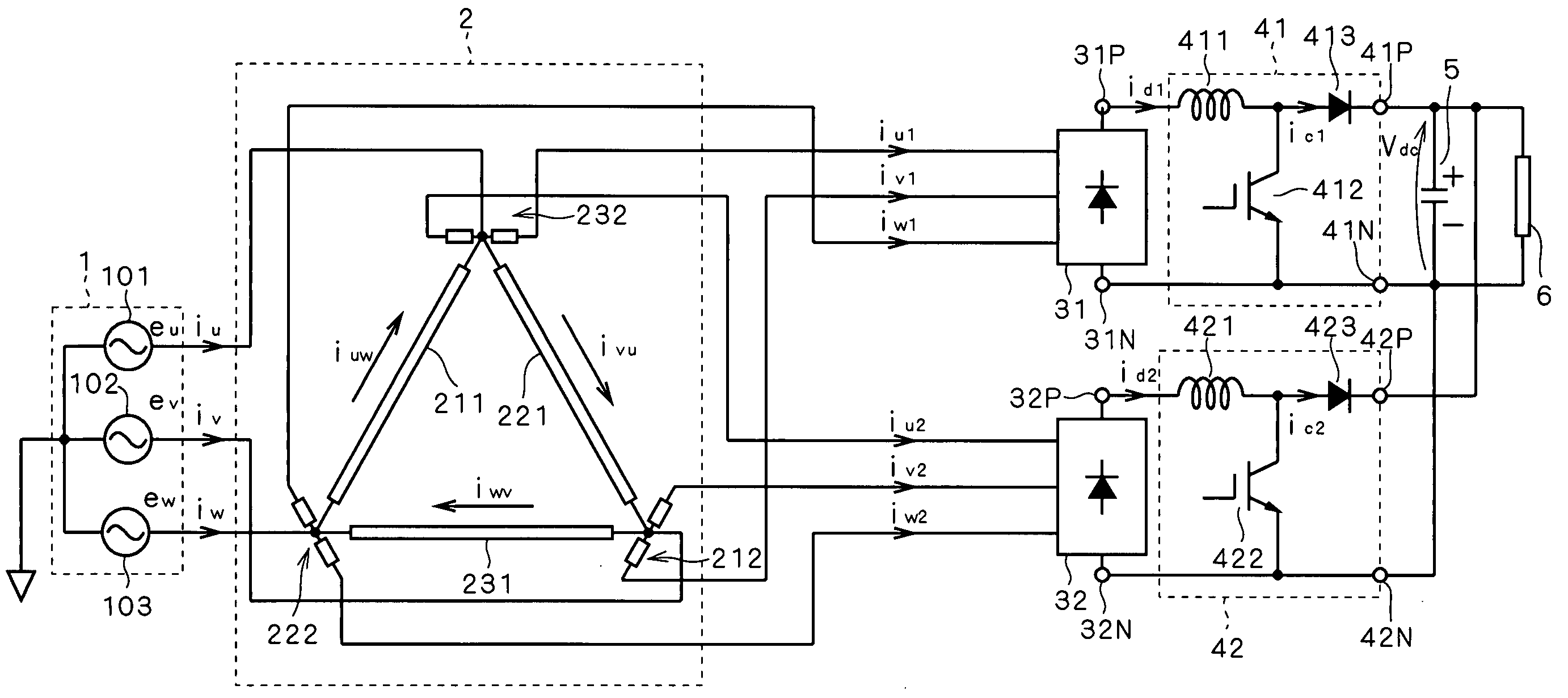
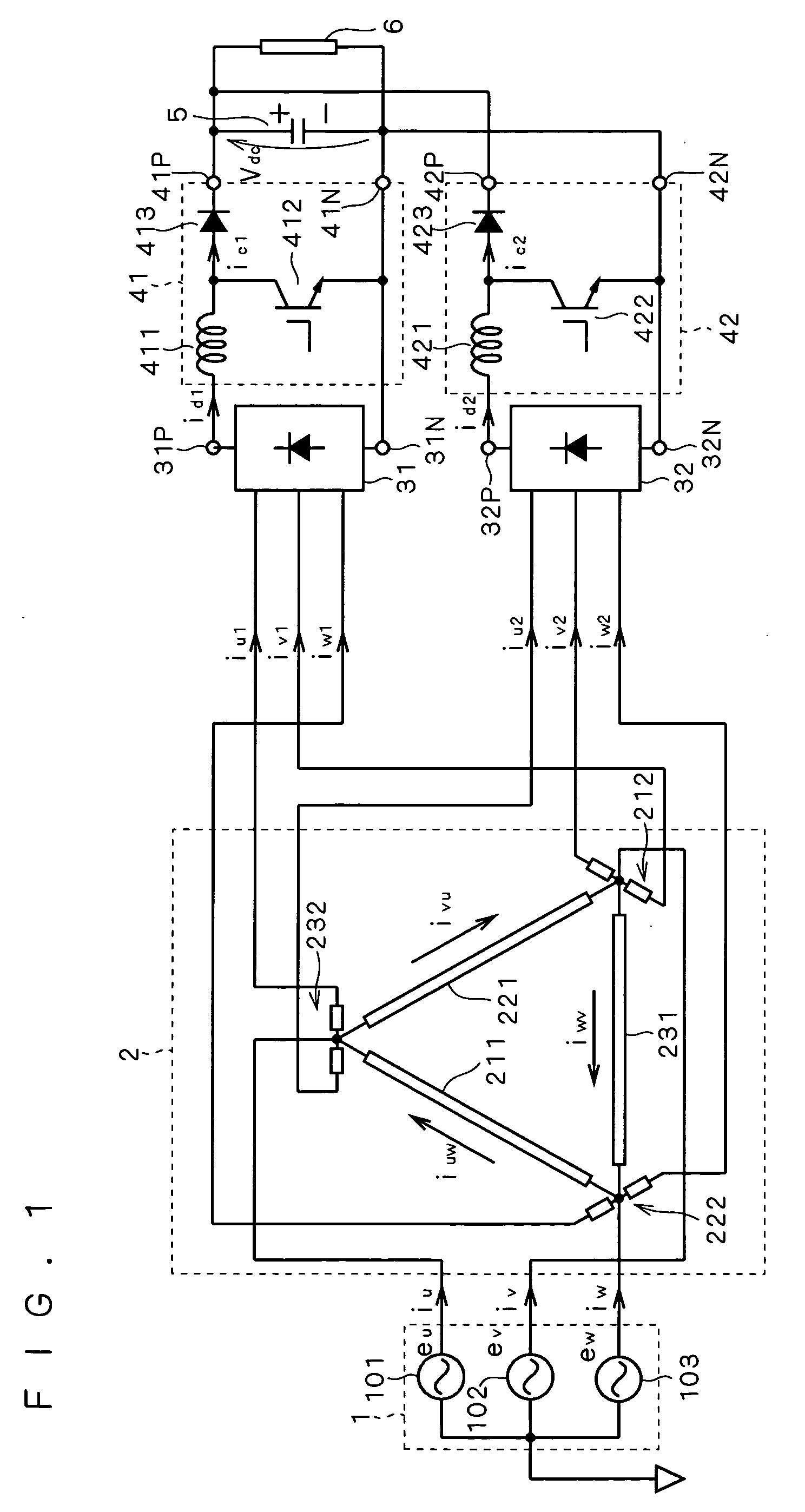
[0054]FIG. 1 is a circuit diagram used to describe a first preferred embodiment of the present invention. A first three-phase diode bridge 31, a second three-phase diode bridge 32, a first chopper 41, and a second chopper 42 constitute a rectifier circuit. The rectifier circuit may be grasped as including a smoothing capacitor 5. A three-phase transformer 2 constitutes a three-phase rectifier device together with the rectifier circuit.

[0055]The three-phase transformer 2 receives three-phase currents iu, iv, iw from a three-phase power supply 1, and outputs first three-phase alternating currents iu1, iv1, iw1 and second three-phase alternating currents iu2, iv2, iw2.

[0056]The three-phase power supply 1 includes a U-phase power supply 101, a V-phase power supply 102, and a W-phase power supply 103, respectively generating three-phase voltages eu, ev, ew. The U-phase power supply 101, the V-phase power supply 102, and the W-phase power supply 103 respectively supply the three-phase cur...

second preferred embodiment

[0102]FIG. 13 is a circuit diagram used to describe a second preferred embodiment of the present invention. The configuration illustrated here differs from the configuration of the first preferred embodiment in that an interphase reactor 71 is additionally interposed between the three-phase transformer 2 and the first three-phase diode bridge 31.

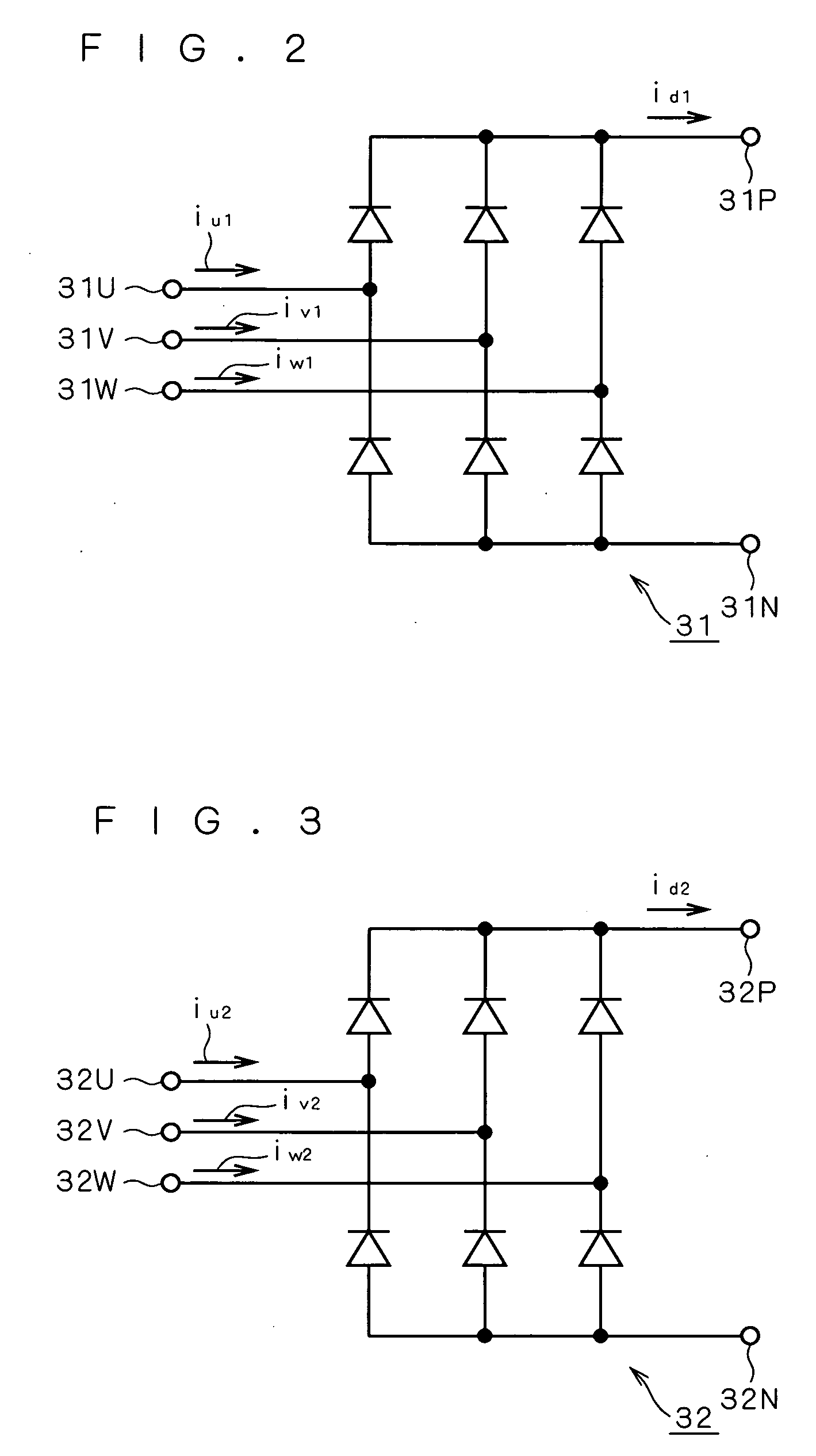
[0103]When explained by referring to FIGS. 2 and 4, the input ends 31U, 31V, 31W of the first three-phase diode bridge 31 are connected respectively to the secondary windings 2321, 2121, 2221, each through one interphase reactor. That is, the three-phase currents iu1, iv1, iw1 flow in the interphase reactor 71.

[0104]Though not described in the first preferred embodiment, zero-phase voltage is generally generated between a neutral point on the input side of a three-phase diode bridge and an intermediate potential on the output side. This voltage is a triple component of the fundamental frequency of the three-phase voltage on the input side. W...

third preferred embodiment

[0111]FIG. 15 is a circuit diagram used to describe a third preferred embodiment of the present invention. The configuration shown here differs from the configuration of the first preferred embodiment in that the first chopper 41 and the second chopper 42 are replaced respectively by a first chopper 43 and a second chopper 44.

[0112]As compared with the first chopper 41, the first chopper 43 additionally includes an inductor 431 and a diode 434. More specifically, the inductor 431 is interposed between the output end 31N of the first three-phase diode bridge 31 and the emitter of the IGBT 412. Also, the diode 434 has its anode connected to the output end 43N, and its cathode connected to the emitter of the IGBT 412. The second chopper 44, too, includes an inductor 441 and a diode 444 that are connected in the same way as the inductor 431 and the diode 434.

[0113]With this configuration, in the first chopper 43 and the second chopper 44, it is also possible to control the currents flow...


PUM


Abstract

Choppers are provided respectively in the output stages of two diode bridges, and their output sides are connected in parallel to a smoothing capacitor. By controlling the operations of the two choppers, the currents which are allowed to be inputted to the diode bridges are made triangular waves of mutually opposite phases, or middle-phase waveforms of three phases.

Description

TECHNICAL FIELD[0001]The present invention relates to rectification techniques, and particularly to a field called multiple rectification.BACKGROUND ART[0002]With the widespread use of inverter equipment, increasing amounts of harmonics are generated due to the loads of rectifiers. This increases the possibility of overheating or breakage of phase advance capacitors and transformers of power systems due to the harmonic current. Therefore, there is a demand to suppress harmonics of the rectified current obtained on the basis of a three-phase power supply (for example, JIS standard JISC61000-3-2).[0003]In a common three-phase rectifier circuit, six steps appear in one period of the current waveform. In general, with an n-step current waveform, the lowest-order harmonic is of the (n−1)th. Then, the harmonic content with respect to the fundamental wave is 1 / n, and so the fifth and seventh harmonics significantly appear.[0004]Accordingly, techniques for suppressing harmonics are proposed...

Claims


Application Information

Patent Timeline
Patent Type & Authority Applications(United States)
IPC IPC(8): H02M5/00
CPCH02M7/12H02M7/08H02M1/4216H02M1/4225H02M3/156H02M5/14Y02B70/10H02M3/155
Inventor OGUCHI, KUNIOMISAKAKIBARA, KENICHI
Owner DAIKIN IND LTD
Why Eureka
Try Eureka