Complex analysis of kinematics for non-hyperbolic moveout corrections

a kinematics and complex analysis technology, applied in the field of seismic data analysis, can solve problems such as information loss, achieve the effects of avoiding “stretching” effects, increasing signal/noise ratio, and improving accuracy and detail

Active Publication Date: 2009-03-12
GEOMAGE 2003
View PDF20 Cites 15 Cited by
  • Summary
  • Abstract
  • Description
  • Claims
  • Application Information

AI Technical Summary

Benefits of technology

[0005]Embodiments of the present invention that are described hereinbelow apply the principles of homeomorphic imaging in processing a group of gathers of seismic signal traces, referred to herein as a “supergather.” The analysis finds moveout corrections adaptively, in a process of complex kinematic analysis, based on parameterization of wavefronts propagating in the subterranean medium. The traces are stacked using these moveout corrections in order to generate an image of the medium, with greater accuracy and detail than are achievable using methods known in the art. These methods described hereinbelow not only increase the signal / noise ratio of subsurface images, but also take into account factors such as changes of velocities in both shallow and deep subsurface regions and curvature of reflecting subsurface layers, as well as avoiding “stretching” effects that occur in methods of moveout correction that are known in the art.

Problems solved by technology

The assumption of hyperbolic moveout, however, is known to be an inaccurate reflection of the actual characteristics of subterranean structures, and its application leads to loss of information.

Method used


Image

  • Complex analysis of kinematics for non-hyperbolic moveout corrections
  • Complex analysis of kinematics for non-hyperbolic moveout corrections
  • Complex analysis of kinematics for non-hyperbolic moveout corrections

Examples


Embodiment Construction

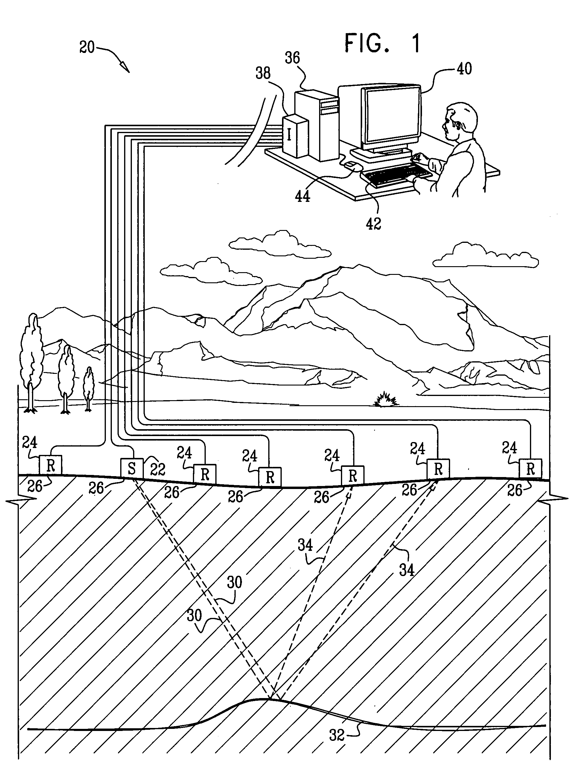
[0036]FIG. 1 is a schematic, pictorial illustration of a system 20 for seismic imaging, in accordance with an embodiment of the present invention. Multiple sources 22 and receivers 24 of seismic signals are distributed at an array of locations 26 on a terrestrial surface 28 overlying a subterranean region of interest. Typically, sources 22 comprise explosive charges, which are detonated at specified times, while receivers 24 comprise seismic sensors, which generate seismogram traces indicating the amplitude of seismic waves reaching the respective locations 26 as a function of time. Although the sources and receivers are shown in FIG. 1, for the sake of simplicity, as lying along a single line (thus defining a two-dimensional acquisition geometry), system 20 typically comprises an array of sources and receivers that are distributed over an area of the terrestrial surface, and may thus use both two-dimensional and three-dimensional acquisition geometries.

[0037]For example, as shown i...


PUM


Abstract

A computer-implemented method for processing data includes receiving a collection of traces corresponding to signals received over time at multiple locations due to reflection of seismic waves from subsurface structures. A measure of correlation among the traces as is computed a function of a set of wavefront parameters, which determine respective moveout corrections to be applied in aligning the traces. A matrix having at least three dimensions is generated, wherein the elements of the matrix include the computed measure of the correlation. Using the matrix, values of the wavefront parameters are identified automatically or interactively along the time axis or along selected horizons to maximize the measure of the correlation, and a seismic image of the subsurface structures is generated by aligning and integrating the traces using the moveout corrections that are determined by the identified values of the wavefront parameters.

Description

FIELD OF THE INVENTION[0001]The present invention relates generally to analyzing the structure of a medium, and specifically to processing of seismic data to analyze subterranean structures.BACKGROUND OF THE INVENTION[0002]Methods of seismic imaging that are known in the art use an array of seismic sources and receivers to acquire data regarding subsurface (i.e., subterranean) structures. Following a seismic stimulus (such as a detonation or mechanical shock) at a given source, each of the receivers produces a seismogram trace, i.e., a record of the seismic signal at the receiver as a function of time, due to reflections of the stimulus wave from the subsurface layers below the array. The traces from multiple receivers due to stimuli by sources at different locations are processed together in order to create an image of the layers.[0003]As part of the imaging process, in order to increase signal / noise ratio, multiple traces from source / receiver pairs surrounding a common midpoint (C...

Claims


Application Information

Patent Timeline
Patent Type & Authority Applications(United States)
IPC IPC(8): G01V1/36
CPCG01V1/303G01V2210/52G01V1/362
Inventor BERKOVITCH, ALEXANDERSCHARFF, NATHANBELFER, IGOR
Owner GEOMAGE 2003
Why Eureka
Try Eureka