
Gateway equipped with a multi-antenna transceiver system with MISO architecture for WI-FI communications

a multi-antenna transceiver and wifi technology, applied in wireless commuication services, modulated carrier systems, polarisation/directional diversity, etc., can solve the problems of manual steering of omni-directional external antennas, relatively high cost, and user manual fitting, and achieve excellent signal reconstruction and high reception level

Inactive Publication Date: 2009-03-12
TELSEY
View PDF7 Cites 20 Cited by
  • Summary
  • Abstract
  • Description
  • Claims
  • Application Information

AI Technical Summary

Benefits of technology

[0019]The purpose of this invention is therefore to realise a gateway that: maintains the advantages deriving from the use of multi-antenna systems with non-directional integrated antennas, is capable of guaranteeing a high level of reception from the signals independently of the position of the gateway in space, is economic to produce, and finally, guarantees excellent reconstruction of the signal received without causing any slowing of the communication every time the transmitting unit is moved with respect to the gateway.

Problems solved by technology

In the first place, the omni-directional manually steerable external antennas, as well as having relatively high costs, require manual fitting by an user, an operation that considerably affects the overall time and cost for the construction of the access gateway.
Additionally, the electro-mechanical coupling between each external omni-directional antenna and the electronic modules that manage the signals transmitted / received from the same may be subject to mechanical slackening and / or electrical decoupling, due for example to incorrect fitting of the antenna, or to the movement of the antenna by the user, conditions that may cause considerable reductions in the gain of the signal supplied by the antenna to the electronic decodification modules on the electronic card.
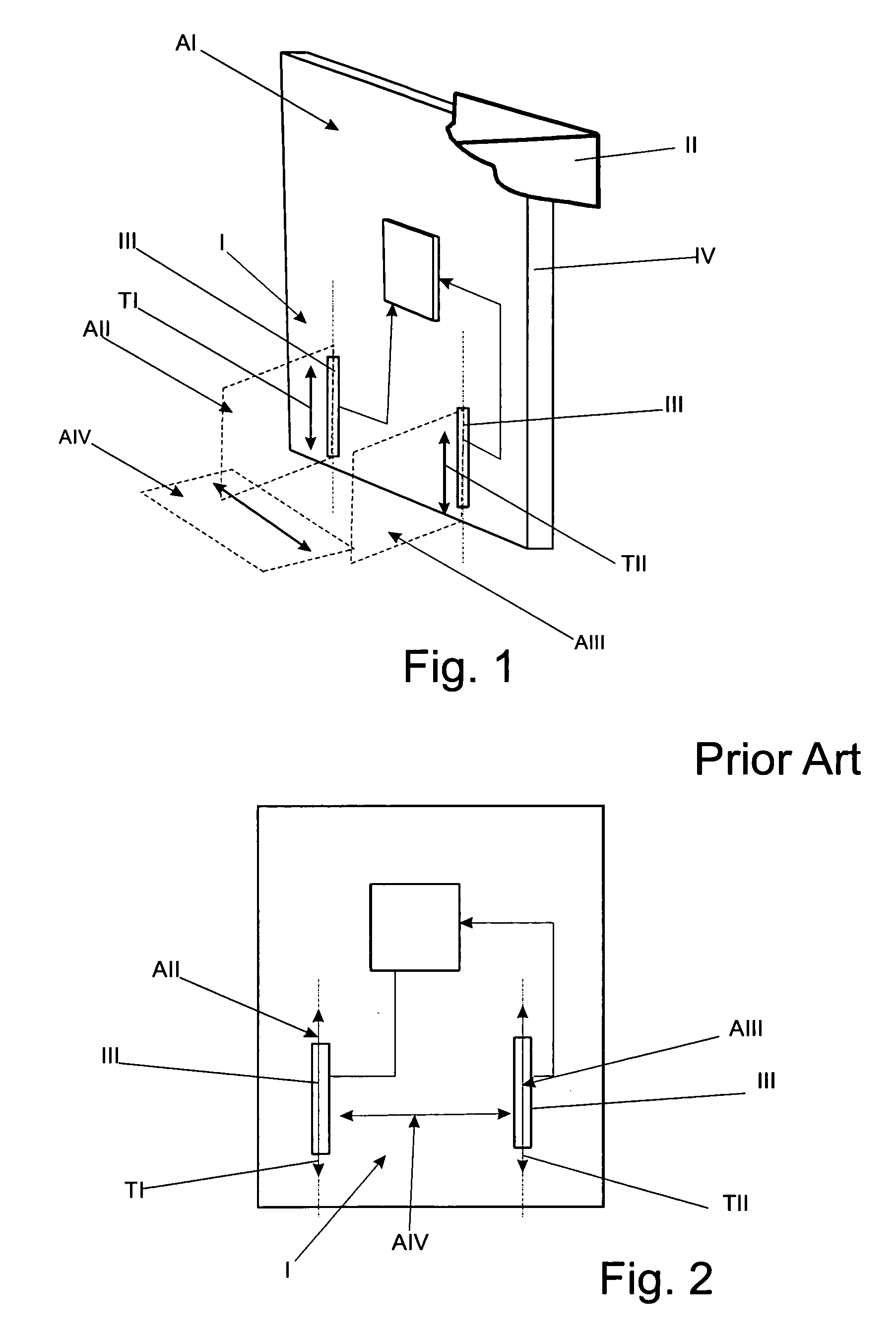
If on the one hand the access gateways equipped with multi-antenna systems with integrated antennas advantageously offer a reduction in the cost of the gateway and, thanks to the absence of mechanical slackening between the antennas and the electric circuits, assure the absence of attenuations in the gain of the received signal, on the other hand it presents the major disadvantage of not guaranteeing correct reception of the signals when the position of the access gateway is not coherent with that foreseen during the design stages.
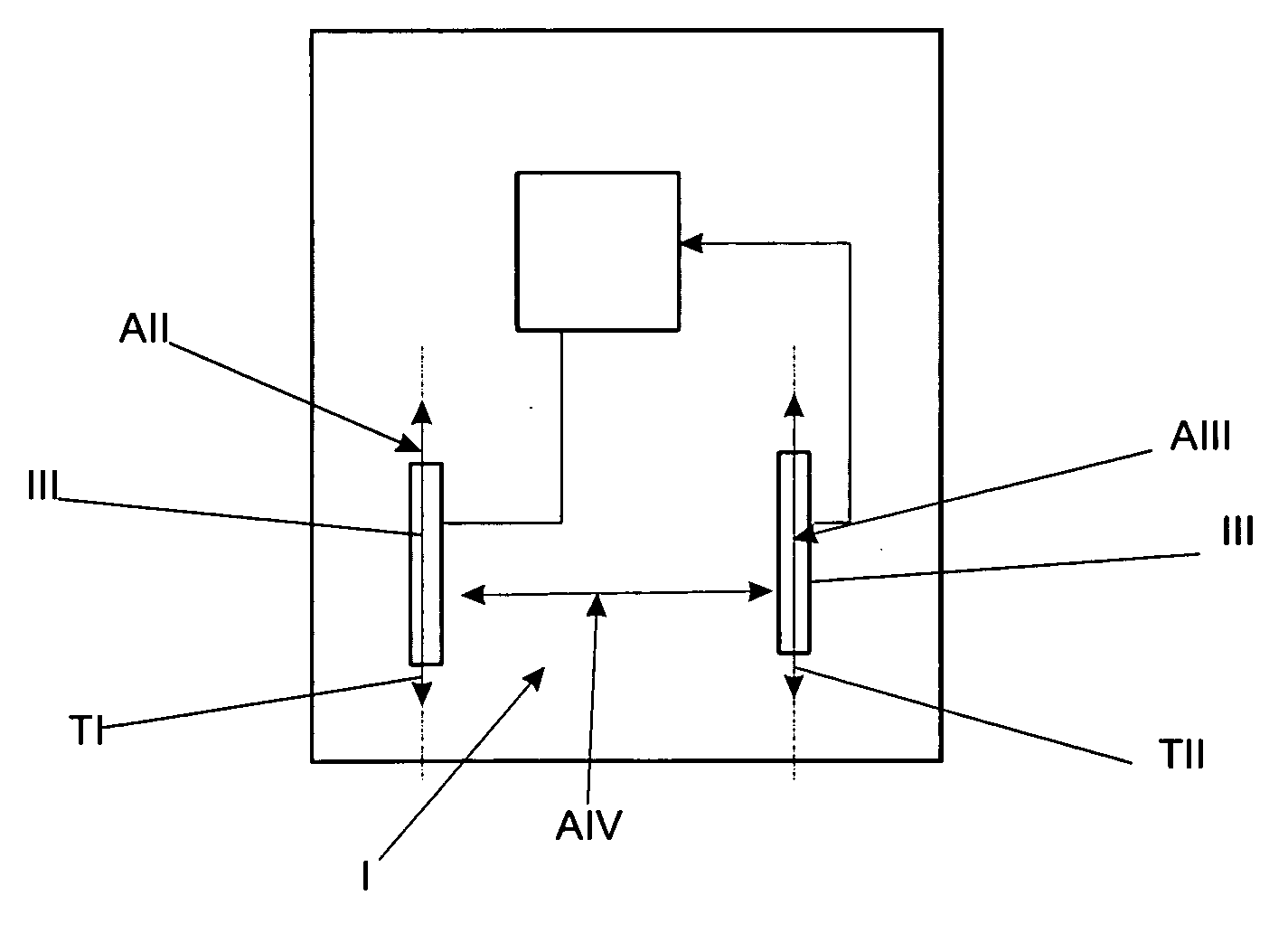
In fact, if the access gateway II is positioned so that the antennas III are positioned in a non-coherent manner, that is not aligned, with the AIV plane of polarisation of the electromagnetic waves transmitted by the Wi-Fi system, the reception of the signals by the antennas III is poor.
The systems described above have the drawback of requiring complex configuration of the antennas which control the switches or the switch devices every time a change is made in the signal transmission conditions by the signal transmission source.
These variations therefore require the system to make a new discrimination ‘in power’ of the signals received by the antennas, and to activate the switches according to the signals received, therefore causing considerably slowing the reconstruction of the signal and consequently the communication.
Moreover, the selection of the antenna on the basis of the analysis of the power of the signals can be extremely disadvantageous when one of the signals is affected by a high-power noise.
In this case, in fact, the system disadvantageously selects a antenna receiving a signal affected by noise, which can prevent any reconstruction of the signal transmitted by the Wi-Fi source temporarily compromising communication.
Finally, the afore-mentioned systems are particularly disadvantageous since they require the use of switch devices for the selection / linking of the antennas and systems for operating the switches, a function which obviously affects the overall production costs for the system itself.

Method used


Image

  • Gateway equipped with a multi-antenna transceiver system with MISO architecture for WI-FI communications
  • Gateway equipped with a multi-antenna transceiver system with MISO architecture for WI-FI communications
  • Gateway equipped with a multi-antenna transceiver system with MISO architecture for WI-FI communications

Examples


Embodiment Construction

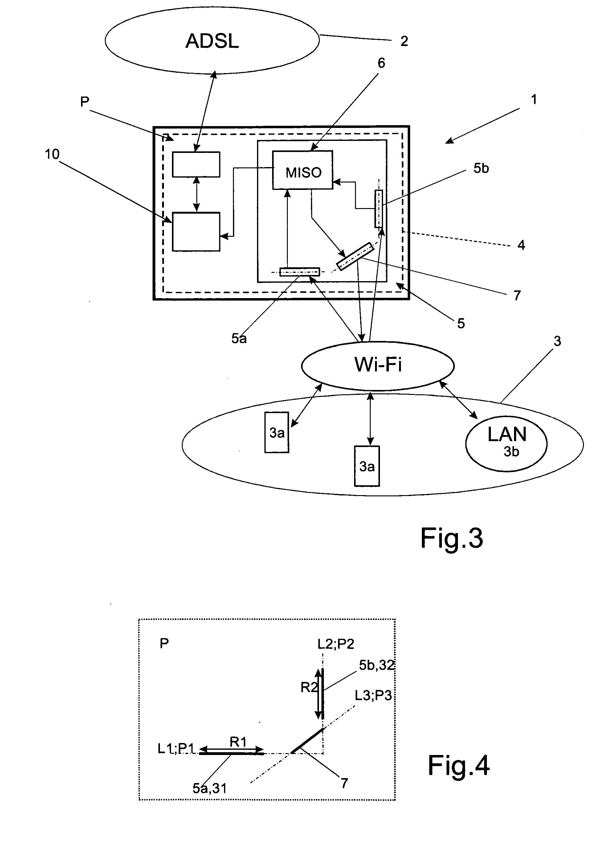
[0039]This invention is based essentially on the idea of constructing an access gateway equipped with an electronic card for communicating with a Wi-Fi system including a Wi-Fi network and / or one or more pieces of Wi-Fi equipment; the electronic card including a multi-antenna system with integrated antennas, which in turn includes at least a first and a second reception antenna fixed permanently on the electronic card, and in which the first antenna is positioned on the electronic card so that its direction of maximum reception lies on a first plane of polarisation, while the second antenna is positioned on the electronic card so that its direction of maximum reception lies on a second plane of polarisation intersecting a first plane of polarization.

[0040]It is opportune to specify that hereinafter the term ‘direction of maximum reception’ of an antenna will be used to mean the direction of polarisation in which it is possible to obtain the maximum antenna gain for an incidental sig...


PUM


Abstract

There is described a gateway including an electronic card (4) and a multi-antenna system integrated in the electronic card for transmitting / receiving radiofrequency signals from and to a Wi-Fi communication system in radiofrequency; the multi-antenna system includes two reception antennas fixed permanently to the electronic card, in which the first antenna is positioned on the electronic card so that its direction of maximum reception lies on a first plane of polarisation, while the second antenna is positioned on the electronic card so that its direction of maximum reception lies on a second plane of polarisation intersecting the first plane of polarisation associated with the first antenna, forming an angle with it equal to or greater than 45; the gateway also comprises a transceiver module realized using MISO or MIMO technology, which is linked to the antennas in order to contemporaneously elaborate the signals received independently by said antennas in order to reconstruct on the basis of the independent signals, the signal transmitted by the Wi-Fi communication system.

Description

[0001]The present invention relates to a gateway equipped with a multi-antenna transceiver system with MISO architecture for Wi-Fi communications.[0002]In particular, the present invention is relative to a gateway equipped with an integrated multi-antenna transceiver, that is with a ‘non-steerable’ antenna, which is configured to actuate a wide band communication with a Wi-Fi transceiver (acronym of Wireless Fidelity), and is made according to MISO technology (acronym of Multiple Input Single Output) or according to the technology MIMO (acronym of Multiple Input—Multiple Output); to which the explanation that follows will make explicit reference, without for this reason lacking in generality.BACKGROUND OF THE INVENTION[0003]As is known, gateways are devices that manage the exchange of data between one or more communication networks and / or pieces of equipment. In particular, the latest generation gateways are configured in order to be capable of carrying out the specific function of ...

Claims


Application Information

Patent Timeline
IPC IPC(8): H04L27/28H04W4/00
CPCH01Q1/2291H01Q1/246H01Q1/36H01Q3/24H04W88/16H01Q21/29H04B7/10H04B7/155H01Q21/24
Inventor PESCE, FRANCESCOCHINO, FRANCESCO
Owner TELSEY
Learn More