Decorative casing and manufacturing method thereof

a casing and decorative technology, applied in the manufacture of electromechanical systems, magnetic recording, record information storage, etc., can solve the problems of limiting the ability to render color, increasing the number of process steps for decoration, etc., and achieve excellent decorative effects, excellent decorative effects, and no more process steps for decoration.

Inactive Publication Date: 2009-03-12
FUJITSU COMPONENENT LTD
View PDF2 Cites 24 Cited by
  • Summary
  • Abstract
  • Description
  • Claims
  • Application Information

AI Technical Summary

Benefits of technology

[0037]According to the present invention, a decorative casing is obtained to which a film having a polarizing characteristic is bonded via an adhesive layer that produces a desired special effect. Accordingly, using a process of bonding the film to the casing, color hue and other special effect can be added. Furthermore, a casing having an excellent decorative effect can be obtained without increasing the number of process steps for decoration. Further, with the color of the casing itself combined with the interference color produced by the multilayer film, coupled with the color hue, etc. provided by the adhesive layer, a variety of excellent decorative effects can be achieved.

Problems solved by technology

This has led to the problem that the number of process steps for decoration increases.
Furthermore, in the prior art, the colored adhesive layer is formed by simply mixing a pigment or the like, and it is only possible to obtain the decorative effect produced by the coloring.
Since other special effects such as color hue cannot be rendered, there has been a limit to how well the color can be rendered.

Method used


Image

  • Decorative casing and manufacturing method thereof
  • Decorative casing and manufacturing method thereof
  • Decorative casing and manufacturing method thereof

Examples


1st embodiment

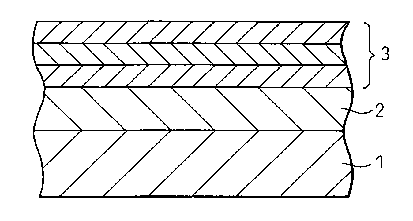
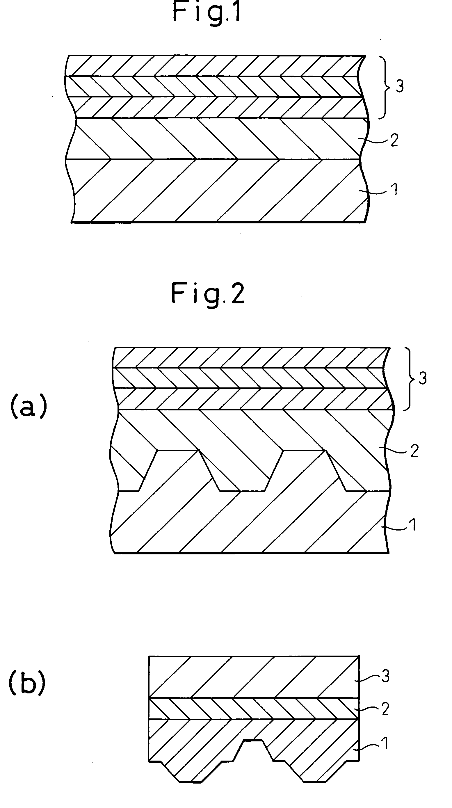
[0050]FIG. 1 shows the decorative casing according to a first embodiment of the present invention. As shown in FIG. 1, the multilayer film 3 having an interference characteristic is bonded to the surface of the body of the casing 1 via the adhesive layer 2. The adhesive layer 2 is formed from an acrylic- or urethane-based resin, and a paint for providing a coloring effect is added as the special-effect material. Preferably, the adhesive layer remains solidified at room temperature, but melts when heated. More preferably, the paint is formed from either an acrylic-based pigment or an urethane-based pigment, or both. In FIG. 1, the multilayer film 3 is shown as comprising three layers, but actually, at least two kinds of thin films having different refractive indexes are formed one on top of another in hundreds of layers. The multilayer film 3 produces an interference color whose hue changes according to a viewing angle. With this structure, highly expressive color hues can be achieve...

2nd embodiment

[0052]Next, a second embodiment according to the present invention will be described. In the second embodiment, the structure of the decorative casing is fundamentally the same as that shown in FIG. 1, but the difference from the first embodiment is that a fluorescent paint is mixed into the adhesive layer 2. The fluorescent paint here can be mixed into the adhesive layer 2 by first adding a powdered fluorescent pigment to an adhesive such as used in the first embodiment and then applying it using a method such as die coating.

[0053]By mixing the fluorescent paint into the adhesive layer 2, the fluorescent effect can be added to the color effects rendered by the base color of the casing 1 and the interference color of the multilayer film 3. As a result, nonconventional highly expressive color hues can be achieved.

[0054]Instead of the fluorescent paint, a luminous paint may be used. An inorganic pigment of alumina-based oxides is preferred for the luminous material. By mixing the lumi...

3rd embodiment

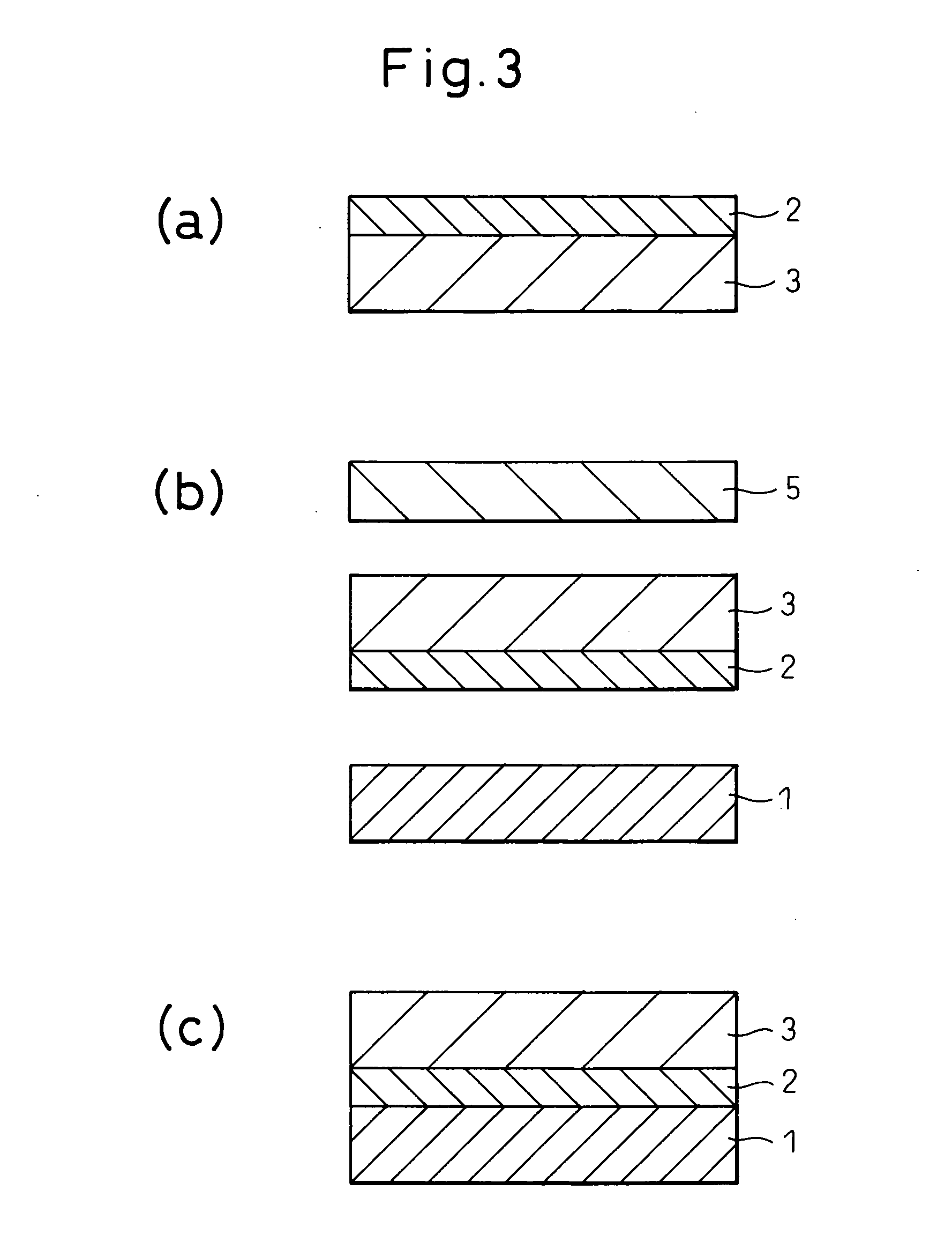
[0055]Next, a third embodiment will be described. In the third embodiment, the structure of the decorative casing is fundamentally the same as that shown in FIG. 1, but the difference is that single color or multiple color paints are added to the adhesive layer 2 to form a marble pattern on the surface of the casing body. More specifically, in the step of forming the adhesive layer by a die coater, a plurality of coloring agents are added to the adhesive dissolved in an organic solvent, and the adhesive is applied over the multilayer film 3 without thoroughly mixing the coloring agents into the solution but by leaving them unevenly dispersed in the solution.

[0056]Since the paints are unevenly distributed in the thus applied adhesive, after removal of the organic solvent the paints are unevenly distributed in the adhesive layer 2, resulting in the formation of a so-called marble pattern. This achieves highly expressive color effects with the uneven coloring of the adhesive layer 2 su...


PUM

PropertyMeasurementUnit
thicknessaaaaaaaaaa
thicknessaaaaaaaaaa
thicknessaaaaaaaaaa

Abstract

The invention concerns a decorative casing fabricated by bonding a film having a polarizing characteristic to the surface of the casing body via an adhesive layer, and an object of the invention is to provide the casing with enhanced decorativeness by designing the adhesive layer so as to render various color effects in addition to the effect rendered by the polarizing characteristic. The polarizing film is bonded to the surface of the casing body via the adhesive layer containing a special-effect material having a color effect. According to the present invention, by directly bonding the polarizing film to the casing via the adhesive layer that produces a desired color effect, other effects such as color hue can be conferred in the film bonding step, and thus a casing having an excellent decorative effect can be manufactured by a simple process without increasing the number of process steps.

Description

CROSS REFERENCE TO RELATED DOCUMENT[0001]This application is a new U.S. Patent Application that claims the benefit of Japanese Patent Application No. 2007-233160 filed on Sep. 7, 2007, the entire content of the Japanese Patent Application No. 2007-233160 is hereby incorporated by reference.BACKGROUND OF THE INVENTION[0002]1. Field of the Invention[0003]The present invention relates to a technique for decorating a casing by bonding a film to the surface of the casing via an adhesive layer. More specifically, the invention relates to a decoration technique for enhancing the decorativeness of the casing by adding a special-effect material to the adhesive layer by which the film having a polarizing characteristic is bonded to the casing.[0004]2. Description of the Related Art[0005]It has been known in recent years to provide a technique for enhancing the decorativeness of electronic equipment, such as a mobile phone, by laminating a decorative film of a polyethylene terephthalate (PET) ...

Claims


Application Information

Patent Timeline
Patent Type & Authority Applications(United States)
IPC IPC(8): B32B3/10B32B33/00B32B3/00B32B37/00B32B38/00
CPCB32B27/36Y10T428/24926B32B2551/00B44C1/17B44F1/04B32B7/12B32B15/18B32B15/20B32B27/06B32B2262/106B32B2262/108B32B2307/416B32B2307/418Y10T428/24868Y10T428/24917Y10T428/2848Y10T428/24612Y10T156/10Y10T428/24802Y10T428/24901Y10T428/24355B32B2451/00
Inventor AKIEDA, SHINICHIROYUBA, TAKASHIARITA, TAKASHI
Owner FUJITSU COMPONENENT LTD
Why Eureka
Try Eureka