Spark plug and internal combusion engine in which the spark plug is disposed

a technology of spark plug and internal combustion engine, which is applied in the manufacture of spark plugs, spark plugs, spark plugs, etc., can solve the problem that the spark plug cannot be installed in the internal combustion engine using a suitable torque, and achieve good heat conduction from the spark plug

Active Publication Date: 2009-03-19
NGK SPARK PLUG CO LTD
View PDF3 Cites 10 Cited by
  • Summary
  • Abstract
  • Description
  • Claims
  • Application Information

AI Technical Summary

Benefits of technology

[0025]Since the spark plug according to the invention described above is mounted in the mounting hole of the engine head in the internal combustion engine according to the present invention, t

Problems solved by technology

When this spark plug is screwed into the mounting hole of an internal combustion engine (engine head), the spark plug cannot be installed in the internal combustion engine using a suita

Method used


Image

  • Spark plug and internal combusion engine in which the spark plug is disposed
  • Spark plug and internal combusion engine in which the spark plug is disposed
  • Spark plug and internal combusion engine in which the spark plug is disposed

Examples


working example 1

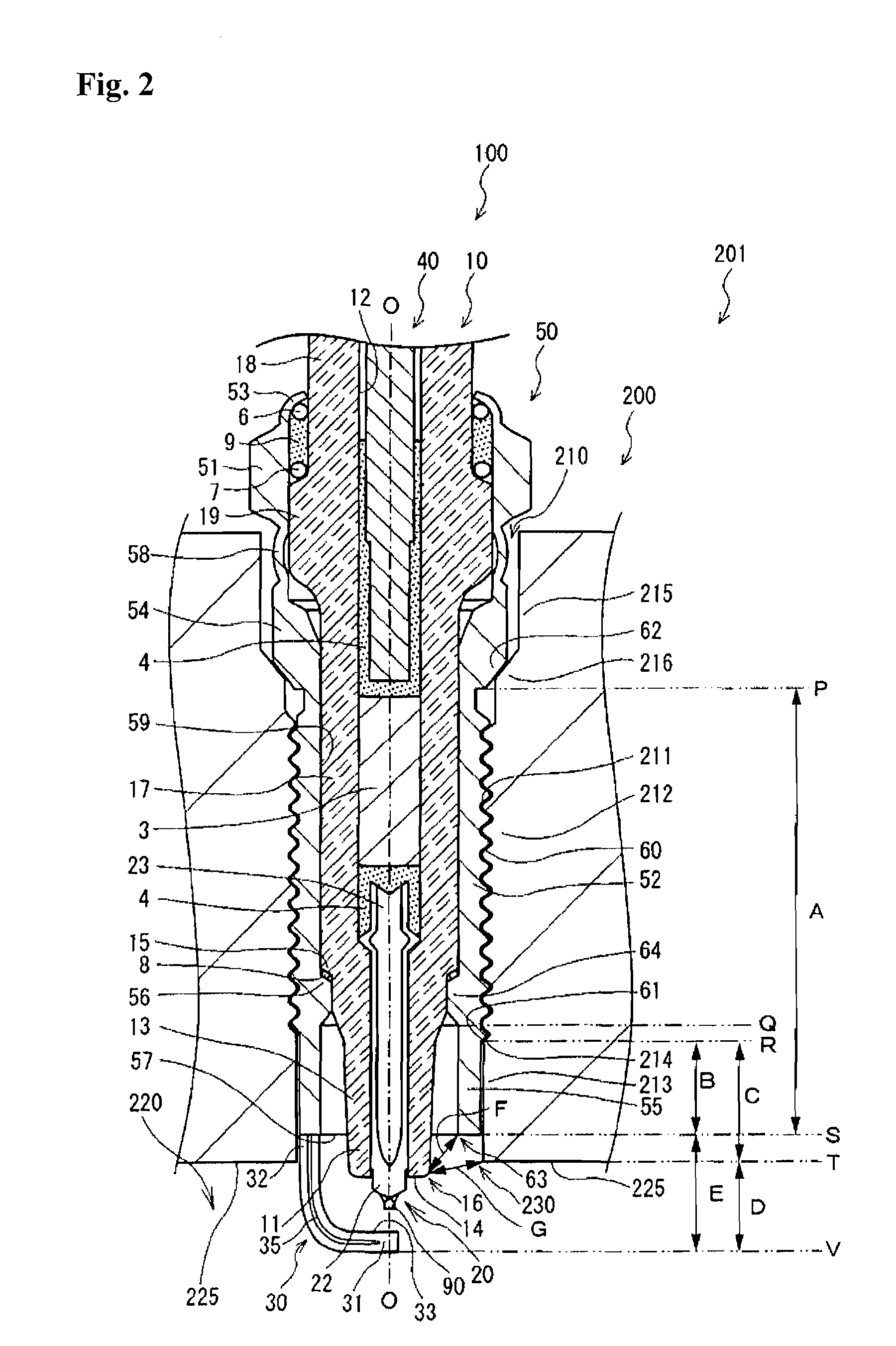
[0066]First of all, the effects on the life (lifecycle) of the engine head 200 by the thermal stress that can occur between the mounting hole 210 of the engine head 200 and the metal housing 50 of the spark plug 100 were evaluated. In this evaluation test, a plurality of spark plug samples where the ratio of length of the cylindrical part 55 to the total length of the mounting part 52 and the cylindrical part 55 (B / A) differed were fabricated and each of them mounted in an evaluation engine. Furthermore, the engine was driven according to a prescribed test pattern, and the lifecycle was found from the travel distance envisioned for each sample when problems arose in the engine head because of the thermal stress arising in the parts of close contact between the metal housing and the mounting hole. The results of this evaluation test are shown in the graph in FIG. 4.

[0067]As is shown in FIG. 4, it was found that the lifecycle increases as the value for B / A increases. Furthermore, when...

working example 2

[0068]Next, the extent the leading end surface 57 of the cylindrical part 55 is recessed in the mounting hole 210 from the wall surface 225 inside the combustion chamber for improving the heat conduction performance of the metal housing 50 was evaluated. In this evaluation test, a plurality of engine head samples where the starting location for the female threads in the mounting hole on the combustion chamber side differed were prepared, and on the other hand, spark plug samples were fabricated with grounding electrodes with embedded temperature probes in the metal housing and a length ratio of 0.2 for the cylindrical part to the total length of the mounting part and the cylindrical parts for the evaluation. Furthermore, an engine was assembled using the various engine head samples, the evaluation spark plugs mounted and run. The temperature of the grounding electrodes was measured at that time. The results of this evaluation test are shown in the graph in FIG. 5.

[0069]As is shown i...

working example 3

[0070]Next, the relationship between the amount of protrusion (D) of the grounding electrode 30 inside the combustion chamber 220 and ignition performance was evaluated. In this evaluation test, a plurality of spark plug samples where the length in the direction of the axial line O from the wall surface inside the combustion chamber to the location closest to the leading end side of the grounding electrode in a range of 2 mm to 7 mm in a state where the spark plugs were mounted in the engine head were fabricated. Furthermore, each of the samples was installed in an evaluation engine (6 cylinder, 2.0 L displacement). A air-fuel mixture with an air to fuel ratio of 14.5 was supplied, the engine was run at 750 rpm, and the firing pressure was measured. The indicated mean effective pressure (IMEP) was calculated by a commonly known method for a single sample from the firing pressures obtained for each cycle. The average value and standard deviation were found from the calculated results...


PUM


Abstract

To provide a spark plug with improved heat resistance and an internal combustion engine in which that spark plug is mounted where there is good conduction of the heat near the opening on the combustion chamber side of the mounting hole for the spark plug provided in the engine and the effects of thermal stress occurring near that opening are mitigated. A cylindrical part without threads formed thereon is provided on the leading end side of a metal housing of a spark plug and the thermal stress applied to a mounting hole is mitigated by avoiding close contact with the mounting hole of an engine head. Furthermore, the spark plug has a mounting structure in which the leading end surface of the cylindrical part is disposed 1.55 mm or more to the base end side in a mounting hole in the direction of the axial line O with respect to the wall surface inside the combustion chamber. By this means, the metal housing does not easily take up the heat that accompanies combustion of the air-fuel mixture inside the combustion chamber at the cylindrical, part so there may be good heat conduction.

Description

CROSS-REFERENCE TO RELATED APPLICATION[0001]The present application claims priority under 35 U.S.C. §119 to Japanese Patent Application Nos. 2007-237563 filed Sep. 13, 2007 and 2008-202734 filed Aug. 6, 2008. The content of the applications are incorporated herein by reference in their entiretiesTECHNICAL FIELD[0002]The present invention relates to a spark plug mounted in an internal combustion engine that ignites a air-fuel mixture and an internal combustion engine in which the spark plug is mounted.BACKGROUND OF THE INVENTION[0003]Conventionally, spark plugs are used for ignition in internal combustion engines such as automobile engines. A typical spark plug has a central electrode that forms an electrode for spark discharge on its leading end side, an insulator that holds that central electrode in an axial hole and a metal housing that surrounds and holds the radial periphery of this insulator. Furthermore, the spark plug is mounted in the engine by screwing the threads formed on...

Claims


Application Information

Patent Timeline
IPC IPC(8): H01T13/02
CPCH01T21/02H01T13/16
Inventor NAKAYAMA, KATSUTOSHIKAMEDA, HIROYUKI
Owner NGK SPARK PLUG CO LTD
Why Eureka
Try Eureka