Power tool

a power tool and variable speed technology, applied in the field of variable speed power tools, can solve the problems of damage to the ring gear or the fixed structure, the rotational ring gear is unable to engage the fixed structure in the housing smoothly, and the operation is not user-friendly, so as to reduce the rotational speed of the movable member, avoid gear clash, and improve the life cycle of the power tool

Active Publication Date: 2009-03-19
POSITEC POWER TOOLS (SUZHOU) CO LTD
View PDF31 Cites 65 Cited by
  • Summary
  • Abstract
  • Description
  • Claims
  • Application Information

AI Technical Summary

Benefits of technology

[0023]By reducing the rotational speed of the movable member, the power tool of the present invention advantageously avoids gear clash on speed variation thereby improving the life cycle of the power tool.
[0024]Preferably the control system is operative to firstly reduce the rotational speed of the movable member and to then actuate the movable member to move from the first position to the second position.
[0025]Preferably the control system is operative to reduce the rotational speed of the movable member to zero.

Problems solved by technology

This operation is not user-friendly.
Furthermore, when the user actuates the actuating member to shift the ring gear from the rotating position to the fixed position, the rotating ring gear is unable to engage a fixed structure in the housing smoothly.
In these circumstances, a gear clash between the ring gear and the rotationally fixed structure frequently occurs which results in damage to the ring gear or the fixed structure and may reduce its working life.
However, these automatic variable speed systems are performed mechanically and the mechanical structure of the systems are complex and difficult to manufacture.
Neither system is able to eliminate the occurrence of gear clash.
It is undesirable that auto speed changing is actuated when the trigger switch is being depressed to increase the motor speed.

Method used


Image

  • Power tool
  • Power tool
  • Power tool

Examples


first embodiment

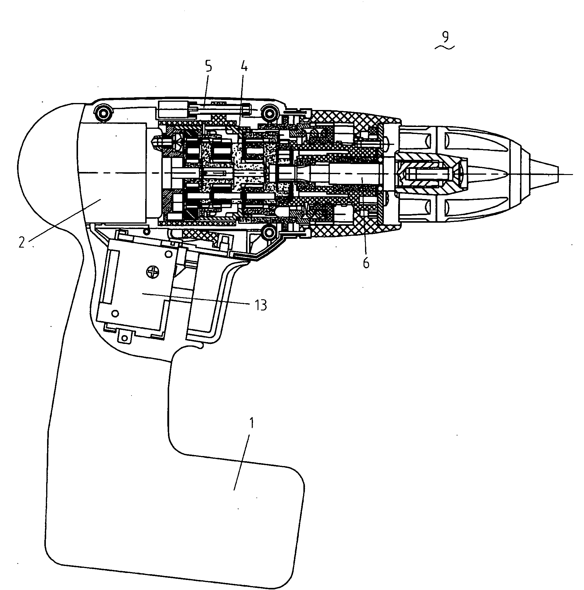
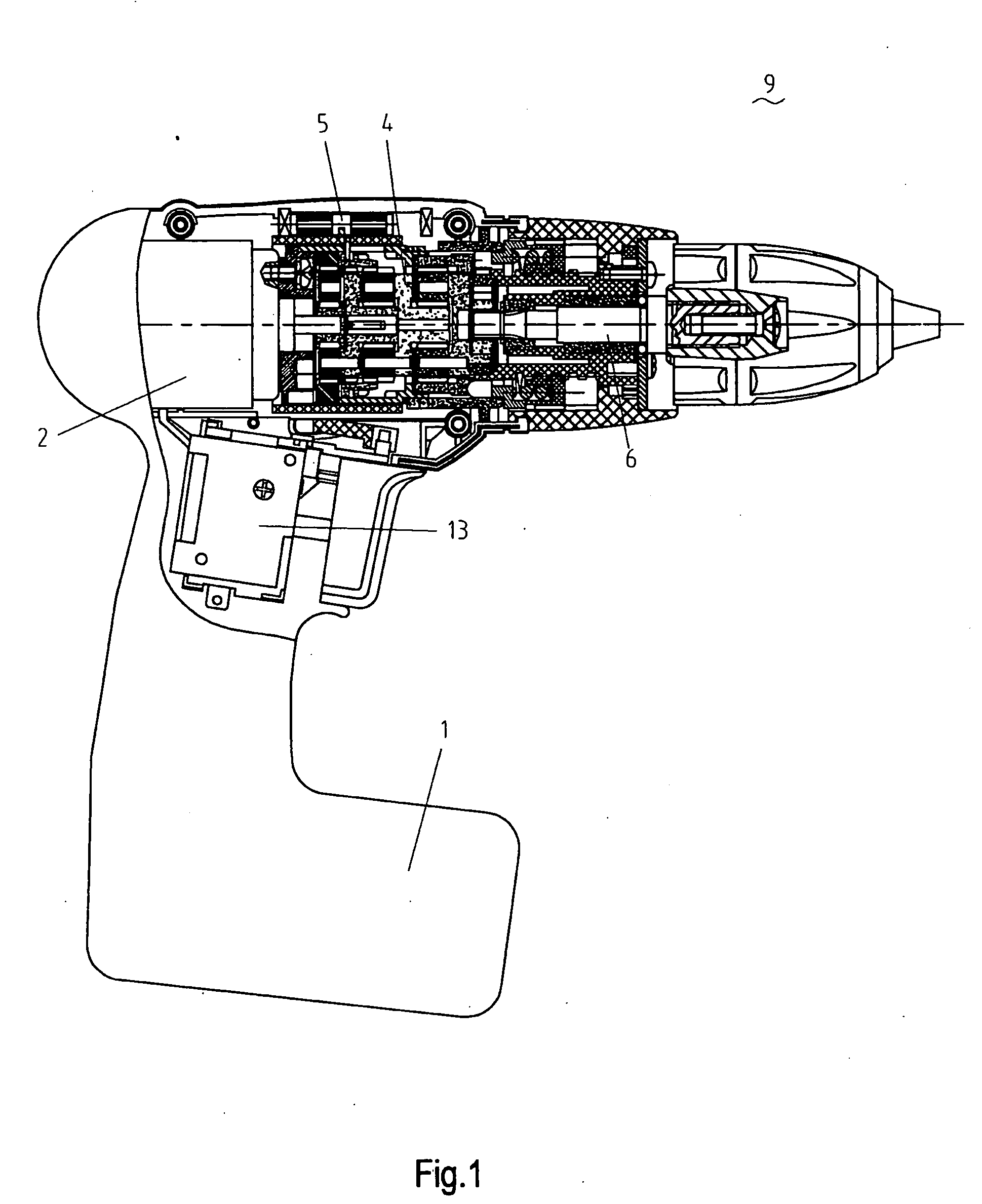
[0084]FIGS. 1 to 3b show a variable speed power tool in accordance with the present invention. The power tool 9 includes an electric motor 2, a power supply 1, a main switch 13 for starting or stopping the motor 2, an output shaft 6 and a gear transmission mechanism 4. The gear transmission mechanism 4 includes a first planetary gear train including a plurality of first planet gears 40 and a first planet carrier 41, a second planetary gear train including a plurality of second planet gears 42 and a second planet carrier 43, a rotationally fixed structure 44 fixed inside a housing 21 and an axially movable member 45. A driving mechanism 5 engages the gear transmission mechanism 4 and includes an actuating device 52 and a transmission member 51.

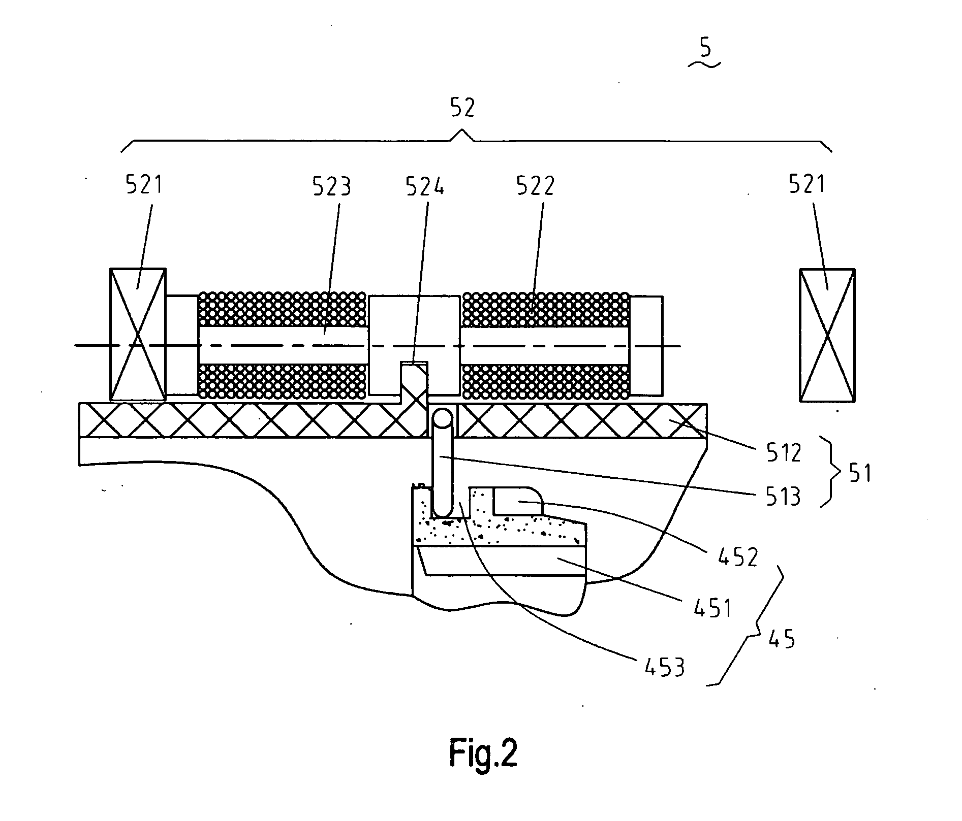
[0085]In the first embodiment, the actuating device 52 is electromagnetic and includes a pair of spaced apart permanent magnets 521, an iron core 523 located between the permanent magnets 521 and a coil 522 around the iron core 523. In the midd...

fourth embodiment

[0108]The signal generator 35 of the power tool of the present invention will be described with reference to FIGS. 15-17. As described above, when the signal generator 35 is activated, the electronic control system changes the direction of the electric current flowing through the driving mechanism 5 thereby activating the speed variation. Referring to FIG. 16, in conjunction with FIGS. 17a and 17b, the signal generator 35 includes a pair of switches disposed on respective halves of the housing 21. Each switch can activate the speed variation. By this arrangement, a left-handed operator and a right-handed operator can conveniently activate speed variation by a single touch of the switch.

[0109]FIGS. 17a and 17b show two forms of the switch. As shown in FIG. 17a, a pushbutton switch 351 is mounted on the housing 21 and a spring plate 353 is mounted on the housing spaced apart and covering the pushbutton switch 351. If the operator wishes to vary the output speed of the running power to...

sixth embodiment

[0114]The power tool of the sixth embodiment is not equipped with a speed mode selector button. Instead, two light emitting diodes (LED) 371, 372 are disposed on the housing 21 for indicating the high speed position and the low speed position respectively. In this embodiment, the power tool starts at a defaulted auto mode. On activating the signal generator 35, the auto mode is interrupted and the speed position will be switched. For example, the power tool initially runs in the auto mode at high speed and the H-LED 371 is illuminated to represent the high speed state. As the signal generator 35 is activated, the auto mode is interrupted and the speed state is switched to and maintained at low speed until the signal generator 35 is activated again or the power supplied to the motor 2 varies. If the signal generator 35 is activated again, the high speed state is resumed and maintained.

[0115]FIG. 20 is a simplified circuit diagram of the control system of a preferred embodiment of the...


PUM

PropertyMeasurementUnit
voltageaaaaaaaaaa
voltageaaaaaaaaaa
voltageaaaaaaaaaa

Abstract

A power tool comprising a housing, a motor, an output shaft, a gear transmission mechanism and a control system. The gear transmission mechanism is connected between the motor and the output shaft to transmit the rotary power of the motor to the output shaft. The gear transmission mechanism has a high speed position and a low speed position. The control system is coupled to the gear transmission mechanism for detecting an operating characteristic of the power tool to actuate a ring gear to automatically move from the high speed position to the low speed position and to reduce the rotational speed of the ring gear when the operating characteristic exceeding a predetermined value.

Description

RELATED APPLICATIONS[0001]This application claims priority under 35 U.S.C. § 119(a)-(d) to Chinese Patent Application No. 200710131762.5, filed Aug. 29, 2007, and Chinese Patent Application No. 200810145304.1, filed Jul. 31, 2008. The contents of these applications are incorporated herein by reference in their entireties.BACKGROUND OF THE INVENTION[0002]1. Field of the Invention[0003]The present invention relates to a variable speed power tool, more particularly to a power tool (such as an electric drill, a screwdriver or an impact drill) having a control system for automatically varying the output speed in accordance with a load applied to the power tool.[0004]2. Description of the Related Art[0005]A variable speed power tool (such as for example an electric drill, a screwdriver or an impact drill) usually employs a gear transmission system to selectively output various speeds to adapt to different work conditions. The gear transmission system generally includes a gear transmission...

Claims


Application Information

Patent Timeline
Patent Type & Authority Applications(United States)
IPC IPC(8): B23Q5/12F16H59/14
CPCB23B45/008Y10T74/19274B25F5/001B25B21/008
Inventor ZHONG, HONGFENGBORINATO, GIANNIZHANG, SHISONGCHEN, CHENGZHONGANDRIOLO, PAOLOLIU, FANGSHIWONG, KELVINBROWN, WARREN
Owner POSITEC POWER TOOLS (SUZHOU) CO LTD
Why Eureka
Try Eureka