Lighting controlling device of vehicle lighting equipment

Inactive Publication Date: 2009-03-19
KOITO MFG CO LTD
View PDF6 Cites 14 Cited by
  • Summary
  • Abstract
  • Description
  • Claims
  • Application Information

AI Technical Summary

Benefits of technology

[0022]As apparent from the above explanation, according to the lighting control device for the vehicle lighting equipment according to one or more embodiments, a loss in respective switching means can be reduced and also it can be suppr

Problems solved by technology

However, no consideration is given to situations in which respective semiconductor light sources (LEDs) are turned ON/OFF individually.
However, when DC currents supplied to respective LEDs are reduced simply directly as a DC current to dim respective LEDs individually, colors of LEDs are changed and occasionally a color

Method used


Image

  • Lighting controlling device of vehicle lighting equipment
  • Lighting controlling device of vehicle lighting equipment
  • Lighting controlling device of vehicle lighting equipment

Examples


fourth embodiment

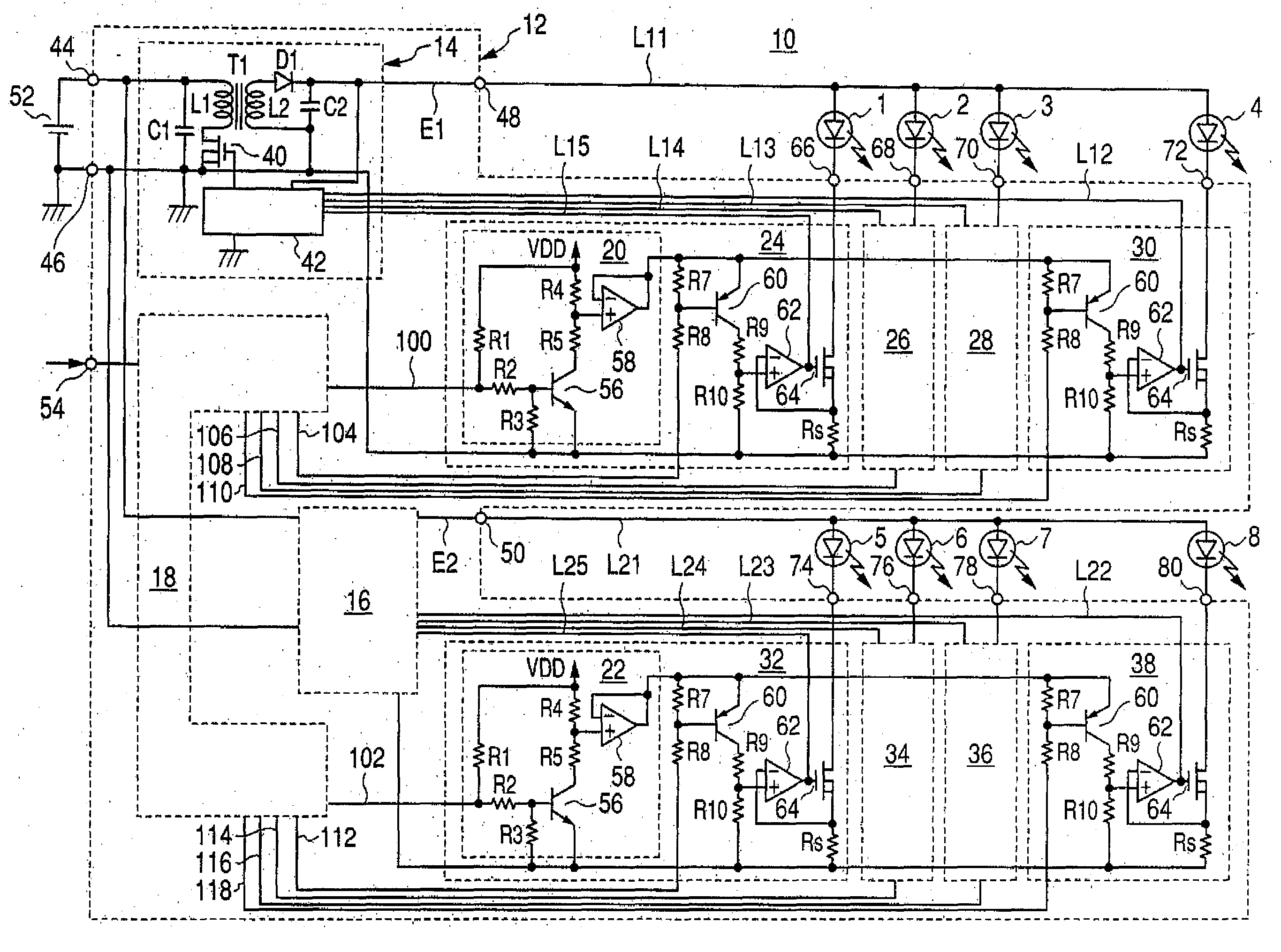
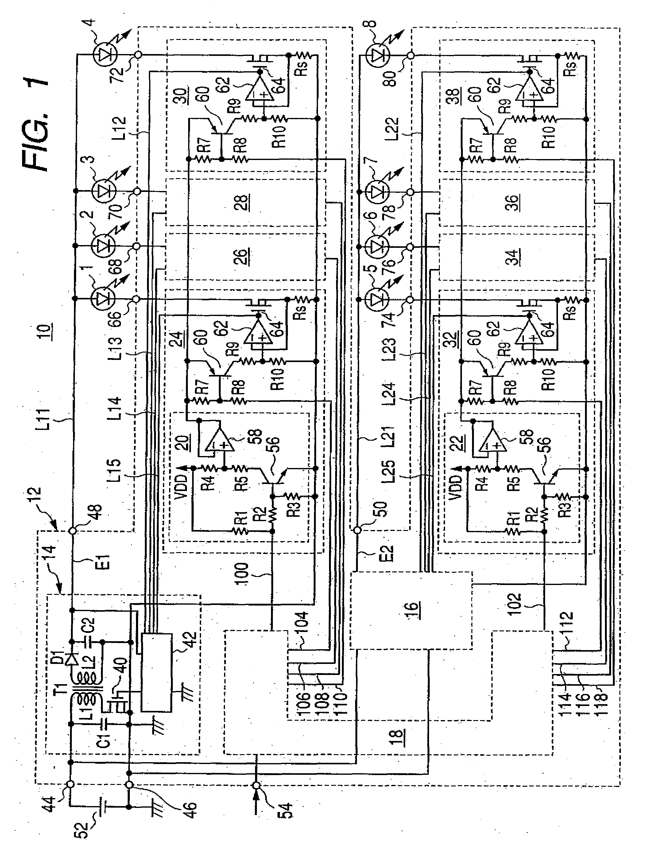
[0101]Next, the present invention will be explained with reference to FIG. 5 and FIG. 6 hereafter. The present embodiment is constructed such that the LED 1 to the LED 4 are connected in series mutually, a current through the LED 1 to the LED 4 is detected by the shunt resistor Rs, and the current flowing through the LED 1 to the LED 4 is feedback-controlled such that the voltage across the shunt resistor Rs can be kept constant.

first embodiment

[0102]Specifically, current driving portions 86, 88, 90, 92 are connected in parallel with the LED 1 to the LED 4 instead of the current driving portions 24, 26, 28, 30, the LED 4 is grounded via the shunt resistor Rs, and the voltage generated across the shunt resistor Rs is fed-back to the control circuit 42 such that a function of the current setting portion 20 is added to the control circuit 42. Except the switching regulator 16 and the driving systems for the LED 5 to the LED 8 are omitted herein, the present embodiment is similar to the

[0103]The current driving portions 86, 88, 90, 92 are constructed by the semiconductor switching element respectively, for example, and also short-circuit or open both ends of the LED 1 to the LED 4 in response to the control signals 104, 106, 108, 110 from the controlling portion 18 respectively.

[0104]As shown in FIG. 6, in order to implement the function of the current setting portion, an error amplifier 94, an NPN transistor 96, and resistors...


PUM


Abstract

A lighting controlling device of vehicle lighting equipment includes switching regulators for supplying a current to a plurality of semiconductor light sources respectively; a plurality of current driving portions, having switching elements connected to the semiconductor light sources for controlling ON/OFF of the semiconductor light sources, for current-driving the semiconductor light sources at a maximum current value or a current value smaller than the maximum current value in response to respective operating states of the switching elements; current setting portion for setting a maximum current value applied in current-driving the current driving portion or a maximum current value of currents fed from the switching regulators to the semiconductor light sources separately in plural stages in response to respective assignments; and a controlling portion for controlling the current driving portion and the current setting portion in response to a plurality of lighting modes based on communication information from an external device. The controlling portion assigns the maximum current value corresponding to each lighting mode to the current setting portion for every lighting mode, and assigns ON/OFF periods of the switching elements to the current driving portion for every lighting mode.

Description

BACKGROUND OF INVENTION[0001]1. Field of the Invention[0002]The present invention relates to a lighting controlling device of vehicle lighting equipment and, more particularly, a lighting controlling device of vehicle lighting equipment constructed to control lighting of semiconductor light sources constructed by semiconductor for light remitting elements.[0003]2. Background Art[0004]Conventionally, lighting equipment using semiconductor light emitting elements such as LEDs (Light Emitting Diodes) as the light sources has been known as vehicle lighting equipment. A lighting controlling device for controlling the lighting of LEDs is included in the vehicle lighting equipment of this type.[0005]As the lighting controlling device, a device equipped with a current driving portion connected in series with LEDs to control LEDs such that a normal current flows though LEDs, and a switching regulator for controlling an output voltage applied to LEDs at a maximum voltage in response to a cont...

Claims


Application Information

Patent Timeline
IPC IPC(8): H05B37/00H05B44/00
CPCH05B33/0845H05B45/10H05B45/385H05B45/46
Inventor KITAGAWA, TAKAYOSHIITO, MASAYASU
Owner KOITO MFG CO LTD
Why Eureka
Try Eureka