View Projection for Dynamic Configurations

a dynamic configuration and projection technology, applied in the field of dynamic configuration projection, can solve the problems of inability to readily apply camera calibration techniques to projectors, limited application to non-specialized fields, and inability to identify and compensate for projection distortion, etc., to simplify the generation of transport matrix t, simplify the implementation, and simplify the effect of light transport matrix

Inactive Publication Date: 2009-03-19
SEIKO EPSON CORP
View PDF7 Cites 57 Cited by
  • Summary
  • Abstract
  • Description
  • Claims
  • Application Information

AI Technical Summary

Benefits of technology

[0034]The above objects are met in a system that simplifies the generation of transport matrix T, simplifies the implementation of light transport coefficients in dual photography, modifies while still further simplifying the light transport matrix T to incorporate compensation for light scattering effects or light noise.

Problems solved by technology

Thus, a key problem that builders of projector-camera systems and devices need to solve is the determination of the internal imaging parameters of each device (i.e. intrinsic parameters) and the determination of the geometric relationship between all projectors and cameras in the system (i.e. extrinsic parameters).
Even after a system has been substantially calibrated, however, the issue of adjusting a projection to compensate for distortions in a projected image is not straight forward.
Identifying and compensating for projection distortion can be a very computationally intensive operation, which has traditionally greatly limited its application to non-specialized fields.
However, since all camera calibration techniques require that the camera requiring calibration (i.e. the imaging device being calibrated) capture a number of images, it would appear that camera calibration techniques cannot readily be applied to projectors since projectors cannot capture images.
While this bootstrapping technique is a tested-and-proven calibration method for projector-camera systems, it is not applicable to the calibration of self-contained projector-camera devices, since it requires the use of pre-calibrated, strategically located, external stereo camera pairs, and thus requires much operator intervention.
Since a digital projector and a digital camera can both have millions of pixels each, the acquisition, storage, and manipulation of multitudes of light transport coefficients can place real practical limitations on its use.
Thus, although in theory dual photography would appear to offer great benefits, in practice, dual photography is severely limited by its physical and impractical requirements of needing extremely large amounts of computer memory (both archival, disk-type memory and active, solid-state memory), needing extensive computational processing power, and requiring much time and user intervention to setup equipment and emit and capture multitudes of light rays for every projection environment in which the projector-camera system is to be used.
However, as is explained above, the high complexity involved in generating and manipulating light transport matrix T has heretofore greatly limited its application, particularly in the field of calibrating projector-camera systems.
Other problems associated with projector-camera systems are how to compensate for light diffusing objects that may obstruct a projector's line of sight.
Of related interest are issues of whether projector-camera systems can be used to achieve more complex images than typical.

Method used


Image

  • View Projection for Dynamic Configurations
  • View Projection for Dynamic Configurations
  • View Projection for Dynamic Configurations

Examples


Embodiment Construction

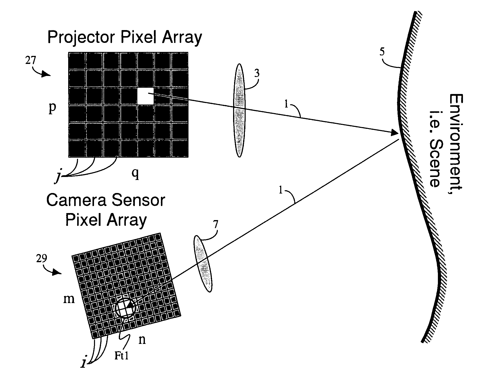
[0133]In order to apply camera calibration techniques to projectors, one would require projectors to be able to capture images. That is, if projectors could capture images, then projector-camera systems could be treated like multi-camera systems, and standard camera calibration techniques (described above) might be used to calibrate projector-camera systems. In other words, if a projector could be treated as a pseudo-camera, then it could be calibrated along with a real camera in a manner similar to the camera calibration stage of the multi-camera system described above, and the “bootstrapping” projector calibration stage previously used for calibrating projector-camera systems might be eliminated.

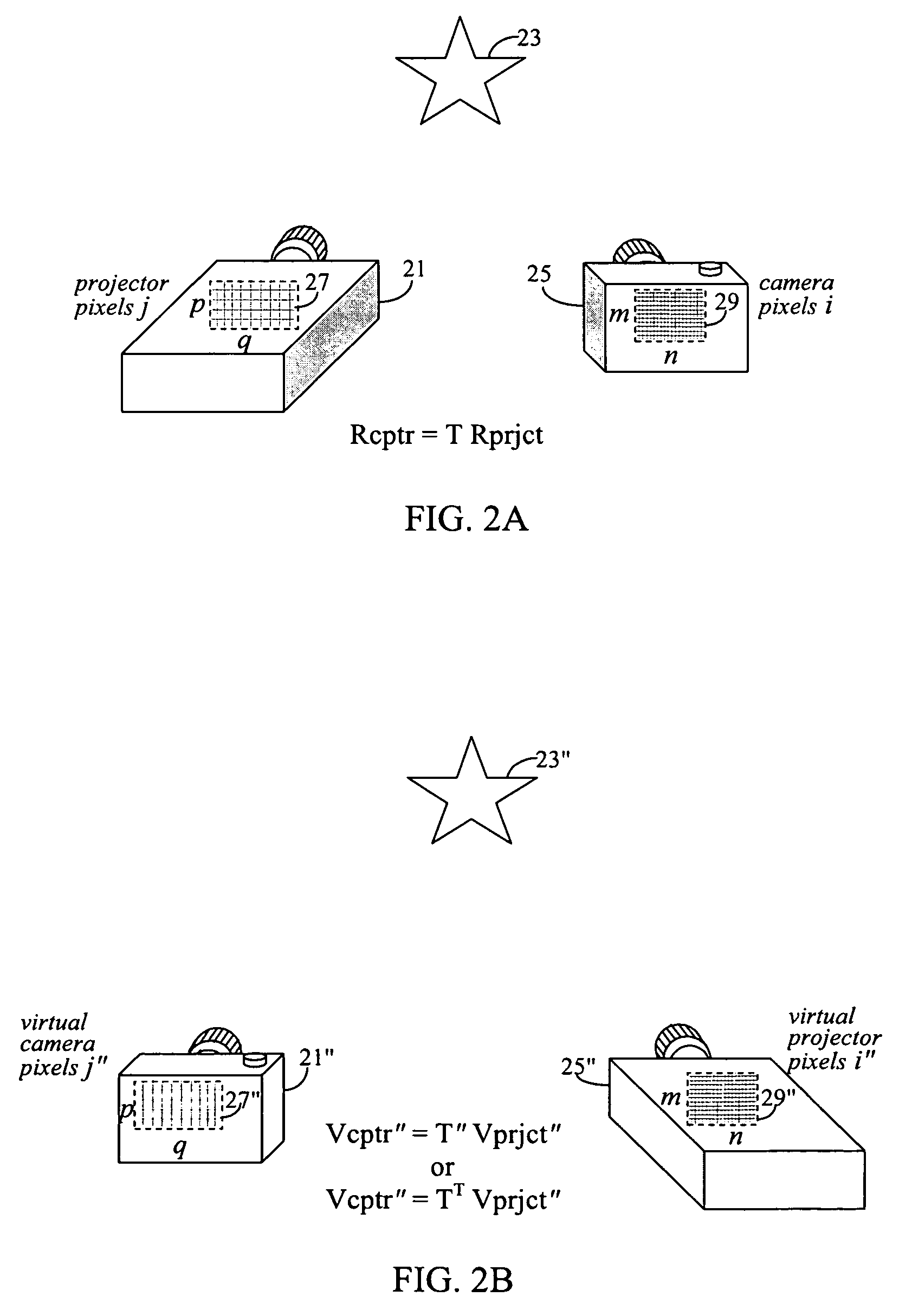
[0134]With reference to FIG. 2A, an imaging setup in accord with the present invention may include a real projector 21 and a real camera 25. Real projector 21 is preferably a digital projector and has an imaging element including an imaging projection array (i.e. projector pixel array 27),...


PUM


Abstract

A method and system for compensating for a moving object placed between a projector and a projection scene is shown. The method/system dividing a movement pattern of the moving object into N discrete position states, and for each of said N position states determining a corresponding view projection matrix. While projecting an image within any of the N position states, multiplying a desired projection image by the corresponding view projection matrix.

Description

CROSS-REFERENCE TO RELATED APPLICATIONS[0001]This application claims the benefit of U.S. Provisional Application No. 60 / 973,351, filed Sep. 18, 2007 under 35 U.S.C. §119(e).FIELD OF THE INVENTION[0002]The present invention is related to methods of modifying projected images to compensate for a moving object in front of a projection surface. More specifically, the present invention is related to methods of compensating for an obstructing object with regular movement in front of a projection surface, and / or compensating for a moving, irregular projection surface.DESCRIPTION OF THE RELATED ART[0003]When projectors and cameras are combined, hybrid devices and systems that are capable of both projecting and capturing light are born. This emerging class of imaging devices and systems are known in the research community as projector-camera systems. Typically, images captured by one or more cameras, are used to estimate attributes about display environments, such as the geometric shapes of ...

Claims


Application Information

Patent Timeline
Patent Type & Authority Applications(United States)
IPC IPC(8): H04N3/26
CPCG03B21/00H04N9/3185H04N5/2628G03B21/005
Inventor TAN, KAR-HANBAGG, EDWARD
Owner SEIKO EPSON CORP
Why Eureka
Try Eureka