Apparatus and method for regulating constant output voltage and current on primary side in a flyback converter

Inactive Publication Date: 2009-03-19
RICHTEK TECH
View PDF8 Cites 55 Cited by
  • Summary
  • Abstract
  • Description
  • Claims
  • Application Information

AI Technical Summary

Benefits of technology

[0010]According to still another aspect of the present invention, circuitry is added for propagation delay

Problems solved by technology

However, due to the forward voltage of the rectifier diode Do and the leakage inductanc

Method used


Image

  • Apparatus and method for regulating constant output voltage and current on primary side in a flyback converter
  • Apparatus and method for regulating constant output voltage and current on primary side in a flyback converter
  • Apparatus and method for regulating constant output voltage and current on primary side in a flyback converter

Examples


Embodiment Construction

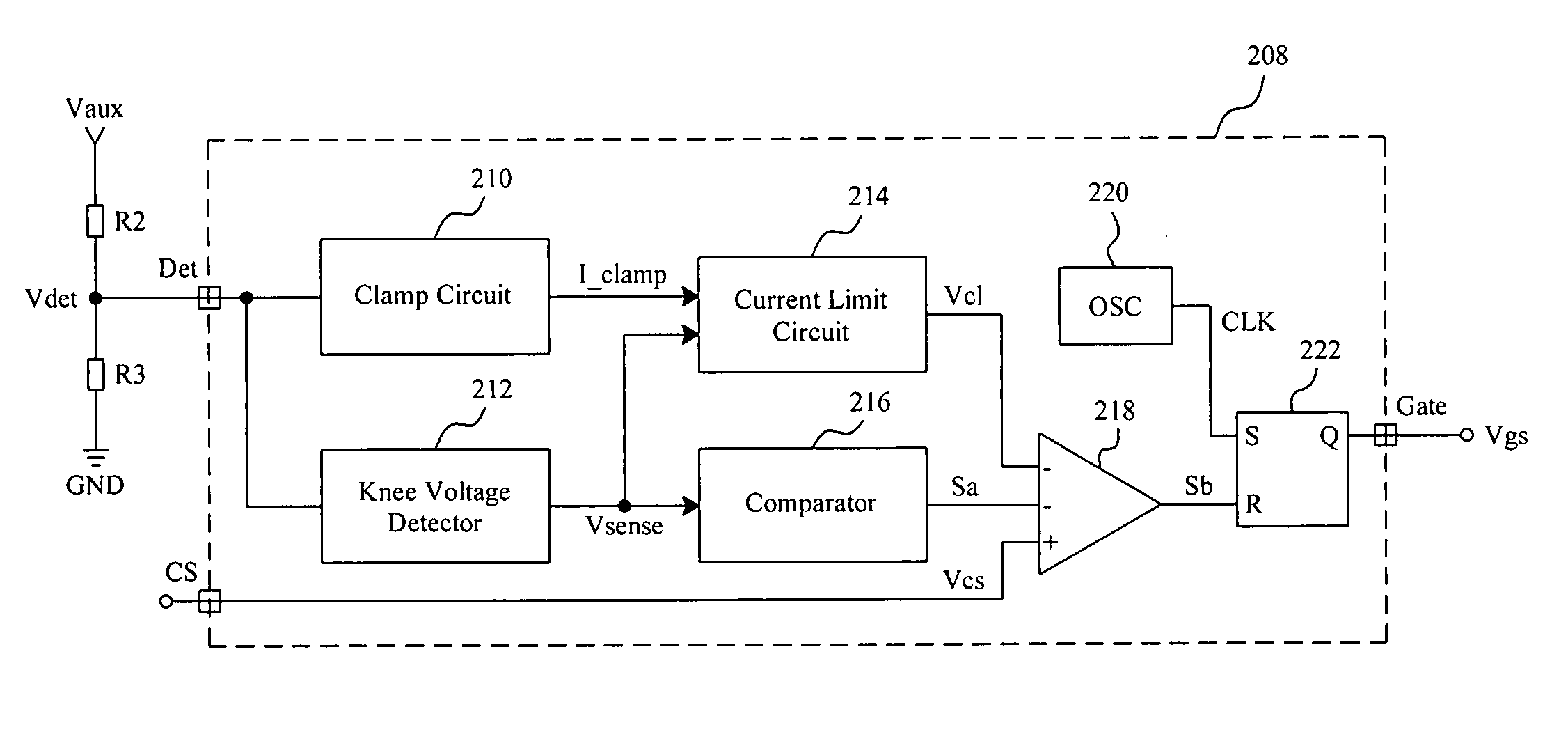
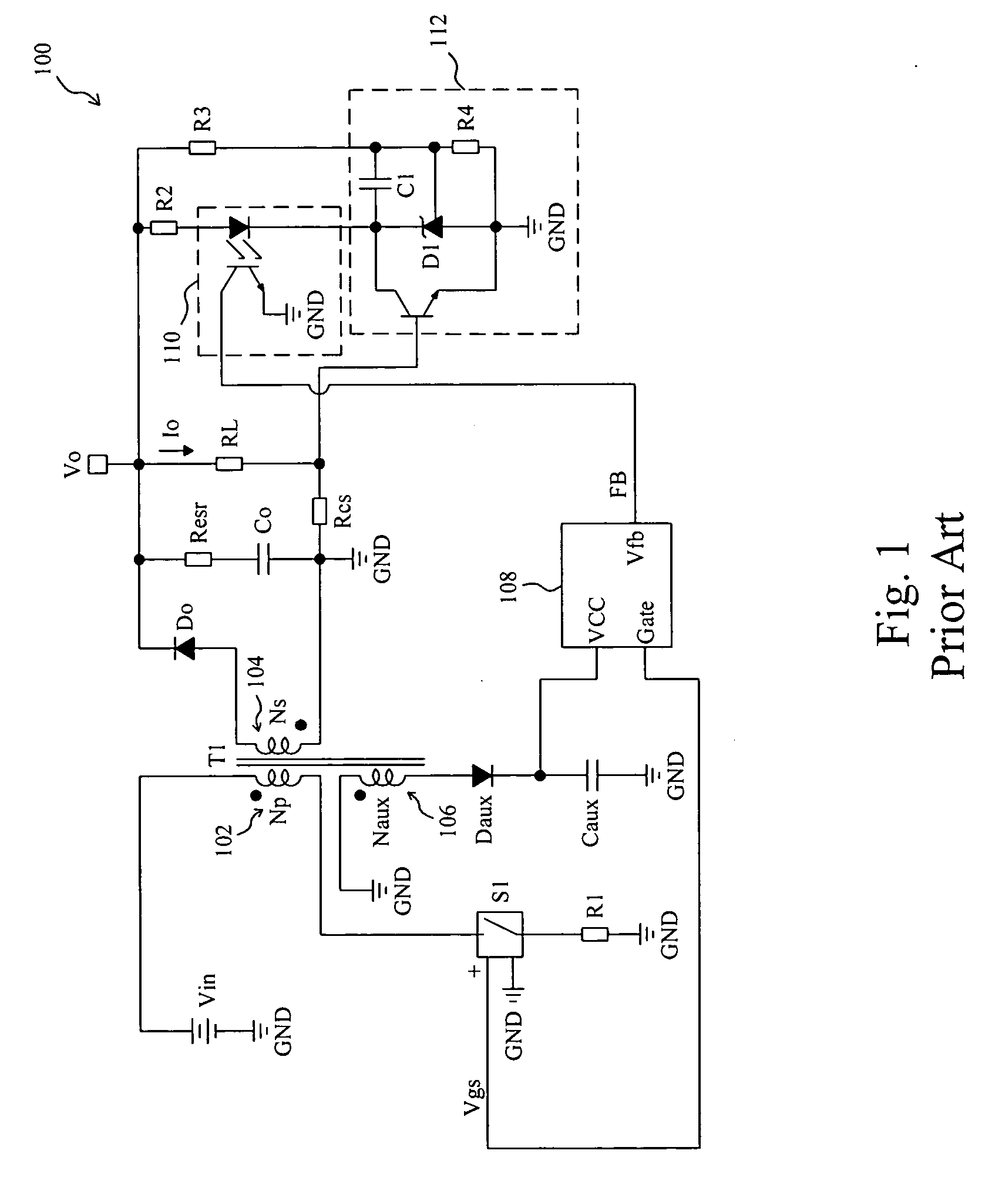
[0023]FIG. 3 is a circuit diagram of a flyback converter 200, in which, as in the conventional flyback converter 100, a transformer T1 has a primary winding 202 coupled between a power input Vin and a power switch S1, a secondary winding 204 coupled between a rectifier diode Do and a ground terminal GND on secondary side, and an auxiliary winding 206 coupled between a ground terminal GND and a diode Daux on primary side, and a controller 208 provides a control signal Vgs to switch the power switch S1 to convert the input voltage Vin to an output voltage Vo. In order to regulate the output voltage Vo and current Io of the flyback converter 200, two resistors R2 and R3 are serially connected between the auxiliary winding 206 and a ground terminal GND on the primary side, serving as a voltage divider to divide the voltage Vaux on the auxiliary winding 206 to produce a voltage Vdet for the controller 208. Since the voltage Vaux is related to the output voltage Vo, output information of ...


PUM


Abstract

A voltage detector circuitry extracts a signal on primary side of a transformer in a flyback converter, which is proportional to the output voltage of the converter without voltage drop on the rectifier diode and leakage inductance effect on the transformer, and good output regulation is achieved without opto-coupler. To accurately detect the output voltage on the primary side, the knee point of the voltage on an auxiliary winding of the transformer is detected. A current limit proportional to the input voltage of the converter is produced from the voltage on an auxiliary winding for stabilizing the output current in constant current mode.

Description

FIELD OF THE INVENTION[0001]The present invention is related generally to a switching mode power supply and, more particularly, to an apparatus and method for output voltage and current regulation of a flyback converter.BACKGROUND OF THE INVENTION[0002]In a conventional off-line switching mode power supply, in order to regulate output voltage and current of the power supply, output voltage and current sensors, such as shunt regulator, current sense resistor and opto-coupler to deliver feedback signal with hazard voltage isolation, are needed on secondary side. In further detail, FIG. 1 shows a conventional flyback converter 100, in which a transformer T1 has a primary winding 102 coupled between a voltage source Vin and a power switch S1, a secondary winding 104 coupled between a rectifier diode Do and a ground terminal GND on secondary side, and an auxiliary winding 106 coupled between a ground terminal GND and a rectifier diode Daux on primary side, and a controller 108 provides a...

Claims


Application Information

Patent Timeline
IPC IPC(8): H02M3/335
CPCH02M3/33523
Inventor LIN, TZU-CHEN
Owner RICHTEK TECH
Why Eureka
Try Eureka